[Plugin] importDXFtext
-
Here's v3.4 again
https://sketchucation.com/pluginstore?pln=importDXFtext
I think I've fixed the typo ?? -
Thanks a lot.
Still the same at the beginning.
Can it be, that the units list returned from the DXF is empty in certain cases?
After I tried with another dxf it worked. And from then on, the first dxf file also worked.Seems to me as if the array is not always initialized.
Other point: I have another dxf which the plugin now identifies being "inch". But this is not the correct unit. It must be meter. Are there multiple units in the file where you can look which unit is the right?
Error: #<TypeError: wrong argument type nil (expected Array)>
C:/Program Files/SketchUp/SketchUp 2021/Tools/sketchup.rb:121:ininputbox' C:/Program Files/SketchUp/SketchUp 2021/Tools/sketchup.rb:121:ininputbox'
C:/Users/Birgit/AppData/Roaming/SketchUp/SketchUp 2021/SketchUp/Plugins/importDXFtext/importDXFtext_code.rb:99:inget_units' C:/Users/Birgit/AppData/Roaming/SketchUp/SketchUp 2021/SketchUp/Plugins/importDXFtext/importDXFtext_code.rb:1880:innew'
C:/Users/Birgit/AppData/Roaming/SketchUp/SketchUp 2021/SketchUp/Plugins/importDXFtext/importDXFtext_code.rb:1894:in `block in module:ImportDXFtext' -
I've tried v3.4 with your very DXF and it works just fine !
Are you installing all of the contents from the RBZ and restarting SketchUp ?
I'll look at forcing the array better - since if seems to partially work !
Watch for a new update...A DXF has one header section - it tells us whether it's English or Metric, and then what the units are, so if it says it's 'inches' it is !
Look for $MEASUREMENT - 2 lines below - there are two choices - 0 is English, 1 is metric
Look for $INSUNITS - 2 lines below - various entries mean different units - e.g. 0=unitless, 1=inches, 2=feet, 3=miles, 4=mm, 5=cm, 6=m, 7=km -
Here's v3.4 again
https://sketchucation.com/pluginstore?pln=importDXFtext
I think I've fixed the array issues ??? -
yes, installed via extension manager and restarted SketchUp.
For the file block.dxf, which shows inch, but in fact should be meter, the entries are:
$MEASUREMENT
70
0
9
...
$INSUNITS
70
1
9for the dxf which causes a crash if loaded as the first file after opening SketchUp, I find:
$MEASUREMENT
70
0
0
...
But there is NO $INSUNITS in this file!What I find is a code without the $ sign:
INSUNITS
350
4CE6
3In a third file, which also works, I have:
$MEASUREMENT
70
0
9
...
$INSUNITS
70
6
9all files have as well Codes called $LUNITS and $AUNITS
$LUNITS
70
2
9
...
$AUNITS
70
0
9Hope this helps finding the cause for error message.
-
@tig said:
Here's v3.4 again
I think I've fixed the array issues ???Now it does not crash anymore when loading the file and I get:
The list of units is set to mm as a default:
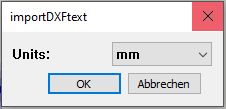
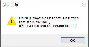
when pressing ok, I get this warning:
When changing the units to something different than mm, I get:
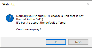
Seems like the units found in the DXF file are "empty": []
With another file lke the block.dxf, I get as the default unit [inches]
-
I think I've trapped it...
The $ codes go in the header
$AUNITS sets units for angles.
$LUNITS sets units for coordinates.Out of curiosity, in the DXF file without the $ in front of INSUNITS is there a section below it starting 70 with a units code number in the line after that ?
If it's missing, it defaults to "/mm depending on the $MEASUREMENTS section... which I tried to fix in the array mess earlier...
The $INSUNITS [if it exists] itself seems to be linked to ACAD design-center blocks units - this seems to overwrite the $MEASUREMENTS section which itself sets English/Metric ["/mm]
Here's the updated version again !

SketchUp Plugins | PluginStore | SketchUcation
SketchUp Plugin and Extension Store by SketchUcation provides free downloads of hundreds of SketchUp extensions and plugins
(sketchucation.com)
-
After the INSUNITS without the $ in front, there is (it is almost at the end of the file (200 lines before EOF)):
INSUNITS
350
4CE6
3
LAYOUTDICT
350
4CE3
3
LWETCUNION
350
4CE5
3
PLOTSETDICT
350
4CE4
3
PSVPSCALE
350
4CEB
3
PUCSBASE
....with the previous version the behaviour was:
If I import the "no unit" file a second time, then the default unit is simply the one with which I imported the file before. Meaning the default unit is not initialized each time a file is chosen.now with the last version, it seems that the "no unit" file defaults to unit Inches.
If I import the file with meters, the warning says the default is inches and the import runs.
If I then import the same file again, the default unit correctly displays again inches and not meter, like before.Nice, thanks a lot.
-
Thanks for the testing and reports.
I've added a 'fall-back' case to the code if the DXF is no formed to ACAD's normal standards, so the PluginStore's version now has that... -
Hi TIG
now that the import is flowing through nicely, I looked at the import result a bit closer.
I found a few minor issues, which would be nice, if they could be resolved.
However, as it takes a bit of time to create a case so you can easily reproduce it, I wanted to ask beforehand, if you will have time and interest to look into it. -
Let me know... I can only say 'no'...
-
@tig said:
Thanks for the testing and reports.
I've added a 'fall-back' case to the code if the DXF is no formed to ACAD's normal standards, so the PluginStore's version now has that...thanks, will download and install and run.
-
-
I have now compared a few files we receive regularly and a lot of the imported text looks fine.
I have compiled below a list of differences and have created a dxf showing these, so that you can readily reproduce the cases. (The dxf file is attached at the end.)The color indications below give the link to the pictures.
The post is a bit lengthy. But for some points I think it took me more time to document than it will take to implement the change in the plugin
Btw, the print screens were done in Trimble connect where I uploaded the dxf file and the skp file with the imported text.Let me know what you think.
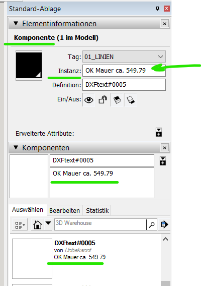
- Currently the 3D-text are all groups. Could instead components be created? Then put the text into the instance name and description (in case too long). Like this we can see the original text in the outliner and component list

-
(Orange marked) it seems that a leading space is not respected. For instance for m², the dxf contains " m".
If I create a 3D-text for " m" manually in SketchUp, this is converted into 3D-text component for "m", but the origin of the component is positioned to the left of the bounding box.
So creating SketchUp 3D-texts as components should solve the issue, if the origin is used to place the 3D text at the position as defined in the dxf. -
(blue marked) a minus sign (dash) as a value of a block Attribute definition is placed too low compared to the text beside it.
See DUMMY_561, which contains a value being a dash "-".
The issue here is, that SketchUp creates a boundingbox around the minus sign and the origin of the created component is on the lower left corner minus sign.
So the minus sign is placed too low.
Possible solution: always add an M at the end or beginning (when aligned right) of the string for 3D-text.
Then shift the origin of the 3d-Text component along the Y-axis to the lower left corner of the M. Then delete the M from the generated 3D text. -
(green marked) some 3D-Texts are positioned a bit too high.
Reason is, that they contain a p, y, j or g and then the lower end of 3D-text bounding box is not on the writing base line.
Currently the lowest point of the letter is positioned on the writing base line of normal text - meaning too high.
This could be corrected by shifting the 3D-text box a bit down. Or if 3D-text components are created, then shift the origin a bit up.
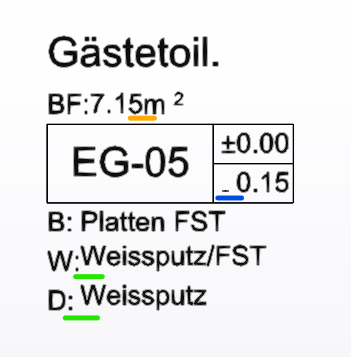
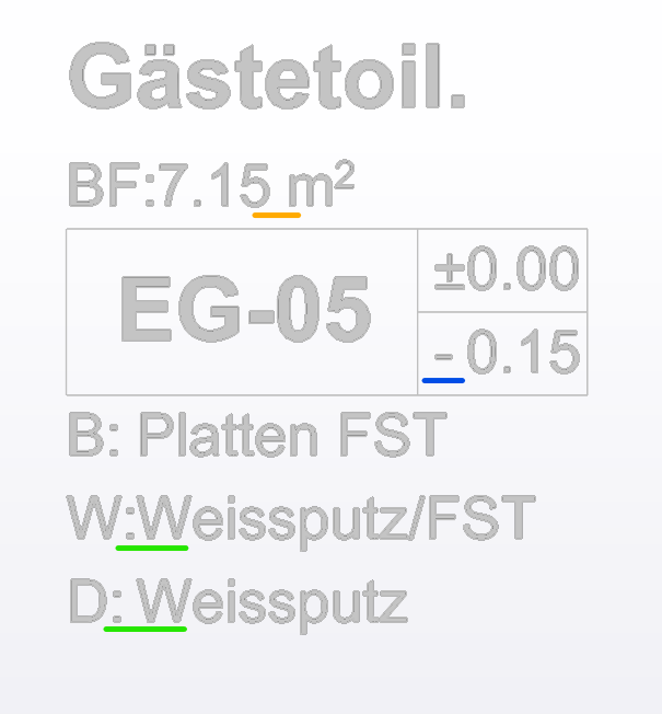
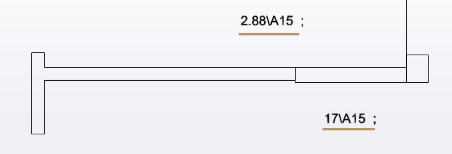
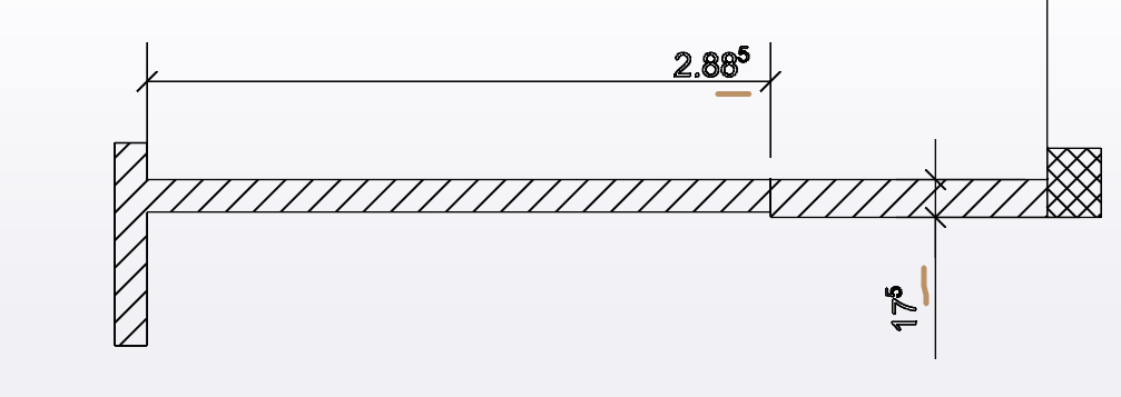
- (brown marked) dxf superscript and subscript commands are not recognized.
Superscripts are used in architetural drawings to indicate the mm number.
"20 superscript 5" means 20.5cm, "2.92 superscript 5" means 2.925m
Does UTF-8 have codes for superscripts which can be used? For example U+2075 (8309) is the unicode number for superscript 5.
See https://en.wikipedia.org/wiki/Unicode_subscripts_and_superscripts
Alternatively a separate 3D-text could be created for the superscript signs like:
Make the superscript or subscript number half the height of the normal text and shift by half a font height up or down. Like this it does not get above or below normal text.
- (purple marked)** add a line break in the 3D Text** so it gets not wider than indicated in the dxf file. Use the MTEXTBEGIN and MTEXTEND definition of the dxf? (assuming this defines the width of the MText box.
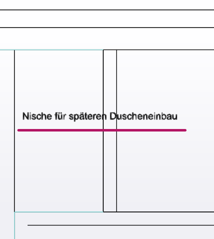

2nd example: (I think this is a bit tricky to implement):


- (grey marked) create SketchUp dimensions from DXF dimensions.
Use only the begin and end point and the position of the line from the dxf.
For the arrow head, just try to figure it out from the dxf and use the Sketchup model default, if in the dxf we cannot find the three possibilities given in SketchUp.
For texts with a line to a point like heights, create a dimension where the line is not offset from the starting point and choose text position "start outside" and no arrow head or a dot.
Or create a radius dimension and type in the text and choose an arrow or point as arrow head.
Set the dimension text in SketchUp to what the MText in dxf indicates.
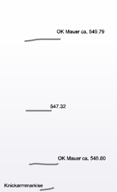
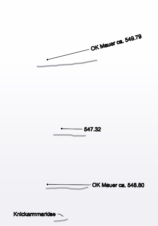
-
(red marked) MText rotated: currently MText that is rotated is not rotated during import. Can this be done?
Currently dimension texts are also always imported as horizontal as they are MTEXTs. Could one rotate the dimension text to be along the dimension lines?
However, if dimensions are imported as such in SketchUp, then this is not important anymore.Btw, text that comes from a block attribute is rotated correctly already.
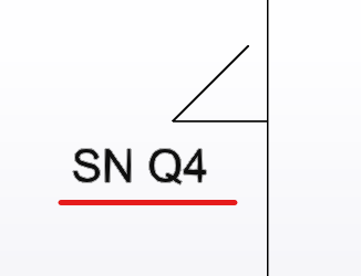
-
ADDRESSED
The following are fixed and will be in an update soon...
'Orange' leading space missed e.g. in m² - first thought because leading & trailing spaces are trimmed [strip] from the text string, but when I thought I'd fixed that issue persisted.
Finally fixed it - silly typo.'Blue' minus sign too low down. Trapped for -ve signs and move them up.
'Green' error - text containing hanging parts set to high.
Trapped for qypgj and shunted up a little.'Brown' superscripts 0-9 now implemented, previously 2 & 3 only.
Similar subscripts have also been added.
BUT unsure why your error shows \A15 as that isn't a Unicode way ?
e.g. it's \U2075 for "⁵" ? Please confirm...NOT YET CONSIDERED.
The group parts could be 'named' differently ?
Or if made as compos, the whole text could be in a description ?
But it does have far ranging ramifications...'Purple' overly long strings split up...
Hard to implement as we've no idea how long the string will format in 3dText.
Looking at MTEXTBEGIN and MTEXTEND ??Dims are also extremely complicated to read/recreate...
Rotated Mtext was meant to be implemented but it has had limitations.
Do you have other example DXF files you could share ? -
Here's v3.5
https://sketchucation.com/pluginstore?pln=importDXFtext
Which includes the tweaks outlined in my previous post... -
Thanks for the quick response.
I fixed the typo in the version and republished v3.5 !I'll need a while to look through your other points...
-
Thanks a lot.
After installing the Plugin, the version text still says 3.4, so I first thought the install did not work. But all fine.
Yes, I have more dxf files. What should they ideally contain?
-
'Orange': Leading space: confirm it works
-
'blue': works for the minus sign.
Tested as well with other chars like: °"*='^`
But these are still placed down at the bottom. -
'green': works nicely
-
'brown': Superscripts. I see no difference yet.
The MText contains for instance the following value string in the dxf:
\A1;{\fArial|b0|i0|c0|p34;2.88\fArial|b0|i0|c0|p34;\A1{\H.66x;\S5^ ;}}The imported result of this is:
2.88\A15I think correctly interpreted is the follwoing part:
\A1;{\fArial|b0|i0|c0|p34;2.88\fArial|b0|i0|c0|p34;.....}But the part \A1{\H.66x;\S5^ ;} is generating the string \A15
I think that the dxf code \H.66x;\S....^ means: by a factor 0.66 of font height shift the string starting after /S upwards (^)-
'components': I would prefer if the 3D-text is created as a component, not a group. The description (not the name) of the component could then contain the text used in the 3D-text. If someone wants to recreate the 3DText manually, only the description has to be copy/pasted into a new 3DText.
If the text would also be used as the instance name, The text would be easily recognizable as well in the outliner. But this is just an option.
The component name (definition) can stay as it is now. -
'Rotated MText': would it be easier, if only a rotation around the z-axis would be considered? I think the rotation angle and the position of the "attach" or "center" point is an attribute in the dxf of the MText.
For me this would be enough, as I import dxf text only for 2D drawings. -
'Purple': Line breaks.
I am not sure, but I thought in dxf there is kind of a column width defined for the MText Codes. Could this be used to estimate the number of characters that fit into the width? For instance assuming an average character in a text is half as wide as high.
Example: if the width of the box is 1500mm and the font height is 250mm, then we can place around 12 chars into the box before doing a line break.
Forget the MTEXTBEGIN and MTEXTEND, I thought this defines the width of the mtext box. -
'Dimensions':
I agree it is not trivial. I was thinking about a pragmatic implementation like: -
get the type of dimension as linear or radial. If the dxf contains a type we cannot map in SketchUp, then ignore it and just import the text as is done today.
-
get the insertion/definition points. But do not try to attach the dimension to an entity.
For a radial dimension, just create a small circle (for type diameter) or arc (for type radius) at the definition point and attach it to the SketchUp radial dimension. Once the dimension is created, delete the circle/arc. -
get the text to be used. (do not let Sketchup set the text)
-
try to figure out the arrow style (none, point, open arrow, closed arrow, dash). If nothing matching is found in the dxf, just use the default arrow style from SketchUp.
-
get the distance of the dimension line (linear) or text (radial) from the definition point(s). I would start with only dimensions in the XY plane. (2D).
(I will try to find out how these dimensions can be drwan using ruby in the general case. In the SketchUp UI I think it is limited to 6 variants: either the dimension measures the X, Y, Z coordinate or the length of the projection on the XY, XZ or YZ plane)
-
-
The
2.88\A15is therefore equal to2.88⁵
I can trap for that, but are there any other decimal parts e.g. 2.88³ ??I see that \A is a DXF alignment code, where 1 is btm, 2 is center, 3 is top
The part after that is the formatted string - e.g. 5
It also has a trailing ; that needs stripping.v3.6 will be published soon and will incorporate that...
I've also added the lone
-alignment/height adjustment to include other lone characters like ` °"*='^`` too... -
Here's v3.6
https://sketchucation.com/pluginstore?pln=importDXFtext
Containing the recent changes outlined in my last post...
Advertisement


