Stitching surfaces
-
More newbie ignorance...
has anyone written or even attempted a plugin that would "stitch" two shapes together along selected edges, deforming as necessary?
I ask because this is a common procedure in sheet metal work (not to mention tailoring, a whole unexplored territory for a tool like Sketchup!): you cut out two shapes -- possibly with curved edges, which makes life interesting -- then using tack welds and tensioning you pull them into a 3-d shape. the shape is predetermined by the behaviour of the sheet material under tension.
a similar effect can be done using soap-bubble, skin, etc., but the difference is that the surface thus created is an interpolation inside (or around) a 3d poly wireframe, and not the actual surface originally drawn, i.e. not the actual sheet of flexible material (in real world terms). the math would be pretty hairy -- we'd have to assume zero stretch, I guess, and even then it makes my brain hurt. but I have seen so many brain-hurting accomplishments in the last couple of days of Discovering Sketchup that I'm beginning to believe these Ruby-speaking geometry hackers can do anything.
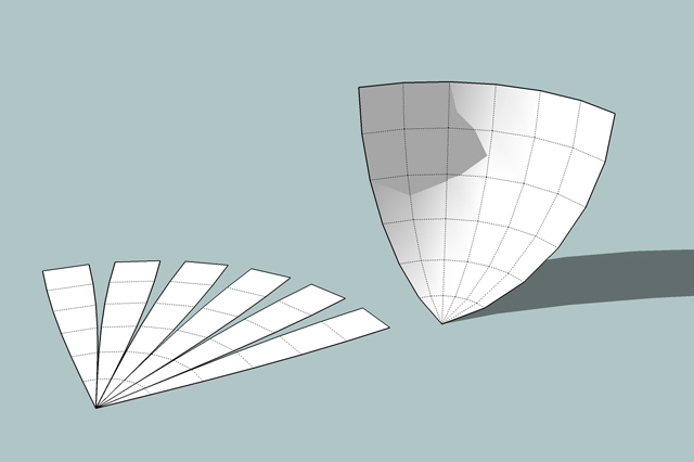
I just wondered if anyone had had a whack at a "reverse unfold" -- something that would create 3d shells out of "peel" segments that started out flat.
dumb question? probably

-
Have you some images of that?
-
Hi Pilou... well here are some photos of the principle applied to a boat hull, aka the "origami method" of hull construction. they are not quite as clear as I would like but I imagine you will get the idea.

flat sheet of steel with cutout "darts" and shape for future contoured seams

one half hull with darted edges stitched up, the other about to be pulled together with comealongs

two half hulls tacked together, bow seam still open

rounded transom tackwelded on, pulling sides into shape

centreline being tacked up, pulling bow into shape

completed hull is fair throughout, no ribs
Similar techniques are used in plywood boat building -- see "Stitch and Glue" -- Sam Devlin wrote a good book about it
here's a typical cut plan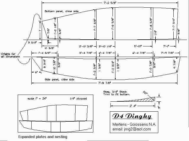
Again the idea is that shaped panels are cut out and their edges married (stitched and glued together), so that the panels deform and under tension produce a monocoque structure, stiff and light. As Devlin's web site says:
@unknownuser said:
The differences between conventional plywood-on-frame and “Stitch and Glue” construction are significant. To better understand the differences between the two, contrast the structural dissimilarities of an early biplane and a modern jet airliner. The biplane was made up of frames and spars over which was stretched a thin skin. The jet airliners structure, on the other hand, is much simpler, with a stressed aluminum skin rigidly attached to bulkheads and spars to create a single monocoque unit. A boat built by attaching plywood planking to lumber frames is most similar to the biplane; a “Stitch and Glue” more closely resembles the jet airliner, a homogeneous structure in which the skin bears the primary stresses.
sorry about the huge images... BBCode img tag doesn't seem to permit scaling...
another example would be the cutting of sails with varying draft: pieces of sail cloth are laid out on the loft floor and cut with curved edges; when the edges are properly married and sewn up, the sail has the right amount of camber, "belly", etc. when filled by wind pressure.
does this explain sufficiently my probably-foolish speculation?
-
I think you are trying to do this the other way round. In SU (in my opinion) you shouldn't "force" what you are doing in real life - starting from flat planes and bending/stitching them together - but first designing the overall shape and then secting it apart to get the basic shapes you can already work with.
But of course, I have never built a boat (do you also build wooden boats?)
-
like gaieus said..
i think it's better to work backwards here (shape first then unfold).. there is an unfold ruby by the way..
-
Cool boats'images

maybe this Script Unfold by Jim Foltz can help you?
It's the inverse but who knows
Ps Don't see the jeff's post
-
@gaieus said:
I think you are trying to do this the other way round. In SU (in my opinion) you shouldn't "force" what you are doing in real life - starting from flat planes and bending/stitching them together - but first designing the overall shape and then secting it apart to get the basic shapes you can already work with.
But of course, I have never built a boat (do you also build wooden boats?)
Not personally
I sail, and live on, a boat built by the origami method. I'd like to model boats of this kind, and it seems like it would be way easier to start with the shape of the steel sheets and mimic pulling them together ('cos I can get good drawings of the steel sheets and their cut lines). I've been fooling about with possible methods of modelling the fair curves of a hull, and it seems there are two ways to go about it (though you guys can probably think of more).One is the method shown in the "model a boat hull" article: draw a couple of bezier curves and use soap/skin to warp a surface around them. The problem with this -- for me as a newbie CADista -- is that (a) the bezier curves while they "look boaty" do not conform to the actual shape of the hull in question, (b) the interpolated surface is hard to predict, (c) the relation of the two original curves in 3-space is a bit confusing to keep track of (d) the original curves need to be 3d, i.e. the "bend" in the line of the toerail is in two axes not just one. It might be better to make a Simple Generic Hull Shape and then use the FFD plugin to bend it this way and that to get closer to the actual lines, but when I tried this initially I found it difficult to get good (rather than amusing or grotesque) results. I'll try again. Practise, practise, practise
The other way to make a hull is to emulate trad wooden boat lofting. This means making a series of frames (vertical slices), lining them up properly, then using "skin" or equivalent to paint a hull around them. I think woodworker Dave Richards talks about using sections + skin to build up nice fair curved components like table legs. A standard wooden (or tradition rib-n-stringer steel) hull would have drawings detailing these sections or frames. But this is not how my boat was made, so I have no drawings for the sections. They could be inferred from careful measurement when hauled out, but...
I guess one more possibility would be to "carve" a boat hull out of a solid: create a giant brick and then scoop away material along carefully drawn paths (using "follow me"? I have not really played with FM yet. It seems potentially powerful, but I'm not sure of its limitations). Alternatively, carve away a big solid with intersects, but either of these means shaping the "cutting tools" for subtractive modelling, which are just as complex as shaping the positive hull form. .
I include here several pics of the boat being hauled for maintenance a couple of years back, to show the complexity and compound curvature of the shapes involved.
note the tumblehome at the transom, i.e. the way the hull sides curve back in towards centreline...

note the extreme sheer, i.e. the upward curve of deck line towards bow and stern away from a low point amidships...

the deck, btw, is also whalebacked (higher on centreline than at the rails, for obvious reasons). the cabin tops are rounded. there is not a flat surface to be seen, except for one bottom section of the hull (dory hulled, with a flat bottom in the region of the twin keels). you can see the hard chine line just above the keel.

the twin keels are vaguely foil shaped and not hard to model (I've already made an approximation of one. the flat dory bottom could be done with an intersect.

It's the very compound shape of the hull that vexes me. Probably the worst problem for a newbie to tackle (something like a cabin or house design, mostly rectilinear, would be a far easier target for a novice!)... but I am not remodelling a house, I'm working on boats
so these nasty, curvy surfaces are what I actually need to deal with. If anyone's got a suggestion for how to model a close approximation of a real boat hull, one with specific measurements and shape, rather than an imaginary boat hull, I am all ears!More pics of Taz under sail, for those who like boats. The sails present a whole other modelling problem
BTW, do smart modellers start from the smallest components and model "upwards", or start with large vague sketchy containers and then fill in detail "downwards"? My instinct is the latter, but for all I know that's stupid and I'll regret it later. Advice?
-
I used to play around with this freeware boat hull designing/modelling softaware "Delftship" http://www.delftship.net/ but for some reason, the website simply doesn't load to me.
These organic shapes will definitely give you hard times in SU as though they are not impossible of course, SU is not the best tool for modelling them (surely many of the plugins will help).
-
Some useful stuff on this page. http://www.carlsondesign.com/
including the Hull Designer software near the bottom of the page (free)It also mentions a design program for sheet metal work, which (I think) is on this page. http://pagesperso-orange.fr/robert.laine/sailcut/index.html
Hello! It looks like you're interested in this conversation, but you don't have an account yet.
Getting fed up of having to scroll through the same posts each visit? When you register for an account, you'll always come back to exactly where you were before, and choose to be notified of new replies (either via email, or push notification). You'll also be able to save bookmarks and upvote posts to show your appreciation to other community members.
With your input, this post could be even better 💗
Register Login


Advertisement