Dealing with Complexly Curved Facades?
-
@fbartels said:
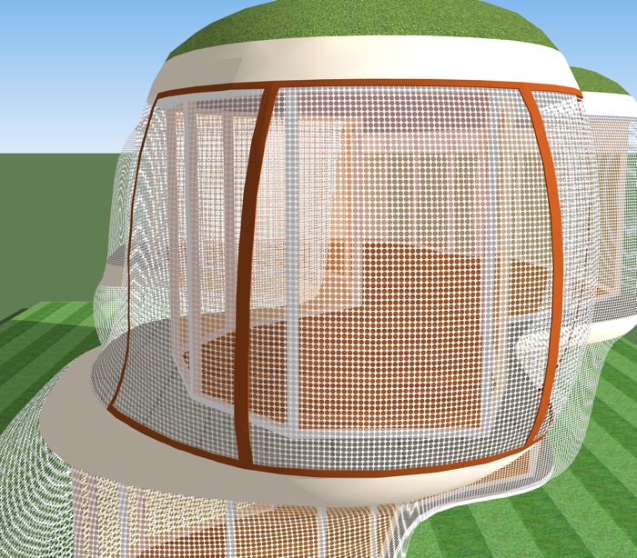
As I've been experimenting (aka playing) with SubDivSmo (SDS) the issue of how to translate the beautiful curves the plugin allows into actual affordable buildable structures has arisen. One concept I've been thinking about is shaped perforated metal sheets as, one might almost say, clothing for the underlying building. (See attached model and images.) The size and shape of the perforations could range widely depending upon the particular context, and could even vary for different locations of a given building. I'm curious what people think of this idea, and what other approaches are being considered.
[attachment=0:1fvyu5xd]<!-- ia0 -->curved facade.jpg<!-- ia0 -->[/attachment:1fvyu5xd]
[attachment=1:1fvyu5xd]<!-- ia1 -->curved facade v2.jpg<!-- ia1 -->[/attachment:1fvyu5xd]
Fred, the issue of making complexly curved surfaces--of the sort you can describe easily with computer modeling--realizable(both buildable and affordable) at architectural scales (building size) is extremely...ha!...complex. It's something I spend a lot of time thinking about.
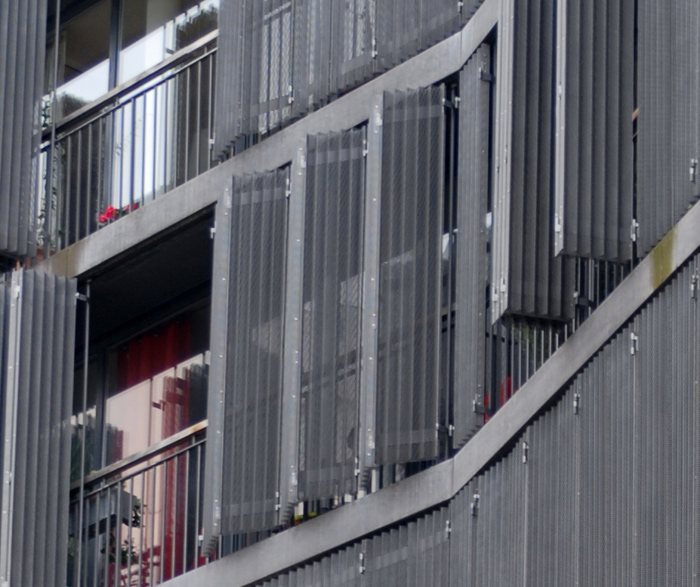
Your idea of "clothing" has been extensively explored, most recently and significantly (in my over-educated opinion) by Thom Mayne of the California firm Morphosis and by the Swiss firm of Herzog & de Meuron. Two of their most interesting recent efforts in this area are in San Francisco (the Federal Building at 1000 Mission Street and the renovated De Young Museum in Golden Gate Park, respectively.)
The greater, more complicated issue of incorporating nondevelopable, complexly-curving surfaces in building facades is explored nicely in these two books:
NCARB Monograph Series: Building Envelope by Randall Stout FAIA:
http://www.ncarb.org/publications/titles/BE.html
and
Digital Design and Manufacturing: CAD/CAM Applications in Architecture and Design by Schodek, Bechtold, Griggs, Kao, and Steinberghttp://www.wiley.com/WileyCDA/WileyTitle/productCd-0471456365.html
One of the issues with creating "beautiful curves" using the SDS plugin is...that they are not really curving surfaces. As with everything else in a mesh modeler, your "curved" surfaces are really a bunch of facets, and this is an unsuitable form of modeling for the study (in all ways except visualization) of complex curvature. That's why architecture firms (like Gehry's, Zaha Hadid's, Morphosis, Greg Lynn's, and so forth) that do this kind of thing regularly resort to NURBS-capable modelers...Rhino, Alias Studio Tools, CATIA, etc.: tools which originally were developed for fields (naval architecture, aerospace, automotive, ID, etc.) where exact description of high-class curving surfaces (that's terminology, not an adjective...automotive design requires "Class A" surfaces, for instance) at any point in their topology is mission-critical.
-
@watkins said:
That looks very interesting, but a step by step tutorial would be even more interesting, unless it is so simple that it is not worth the effort. Did you start with a flat mesh and then deform? Do the dimensions of the mesh remain unchanged when you deform? Perhaps I am being a little dense, but how do you use SDS in this context?
Bob,
Regarding making, no need for a tutorial. I just intersected an exploded curved TIN surface with a bunch of rectangles (actually, one component rectangle duplicated many times) and then deleted the rectangle shapes from the TIN surface. Regarding SDS, this model was meant to represent a subsection of a larger curved building shape that would be created using SDS... something like the following.
Fred
-
@lewiswadsworth said:
Fred, the issue of making complexly curved surfaces--of the sort you can describe easily with computer modeling--realizable(both buildable and affordable) at architectural scales (building size) is extremely...ha!...complex. It's something I spend a lot of time thinking about.
Lewis,
Could we talk about an online architecture course? I'm in if you are interested.
Lots of good leads to follow up, thanks for those!
Lewis, is it possible to export SketchUp files into one or another of the NURBS-capable modelers?
Thanks,
Fred
-
Fred, as far as im aware its very difficult/imposible to convert a polygon model to a nurbs model. This is basically because nurbs surfaces are perfect and exact whereas curvy polygon surfaces are just approximations.
For this reason it's pretty easy to convert nurbs to polgons, although thats not a lot of help to us SU users.
Brin on nurbs modelling in SU (not that its ever going to happen )
-
@fbartels said:
@lewiswadsworth said:
Lewis, is it possible to export SketchUp files into one or another of the NURBS-capable modelers?
Yes and no. Some NURBS platforms will bring your SU model in as a "mesh object", which only allows limited modification. Or they will convert each mesh face into a single NURBS surface. For instance, Rhino will allow you to import every polygon as a trimmed NURBS surface.
However, that doesn't really solve your problem...you're just exchanging every polygon facet for a flat NURBS.
It works better to export only edges (including cross-sectional edges) from your mesh modeler (like SU) into your NURBS modeler. Then you can usually use the surface tools in the NURBS modeler to recreate your "complex" mesh surface as a single or collection (polysurface) of NURBS that approximate it.
Since SketchUp doesn't really work with splines, you can still end up (even if you import your edges for your complex surface only) with something that is not quite as smooth as you would like as a NURBS. In general then you have to get into rebuilding or changing the degree of the imported edges in the NURBS modeler to create a smoother curve for generating surfaces.
Now this is the kind of thing that is true for Rhino and similar NURBS beasts...there is a simple, intuitive NURBS modeler called Moment of Inspiration which forces a lot of the tedium into the background, at the cost of some of the precision and refinement you can get with the higher-end modelers.
There are some Dinosaur modelers, like FormZ and Maya, that will make and edit NURBS and mesh objects equally well, but there is usually some awkwardness if you attempt to use both types of objects within the same file. Or at some point, to make all the objects interact properly you will have to convert everything in the model back into meshes.
-
By the way, NURBS vs. Mesh is only part of the story.
There's another whole argument about surfaceversus solidsmodeling. People who use solid modeling (and who, in general, have shelled out hugesums of money for the programs) tend to believe that anything modeled with either NURBS or meshes lacks sufficient "integrity" for realization. SpaceClaim is an inexpensive solid modeler with a SketchUp-like interface.
-
To get 'exact' curves for production, even Rhino is considered not being accurate enough as a NURBS modeler. I think people will use Solidworks or other soft like Catia as Lewis said when things need to go into real life production.
Another thing about getting curved surfaces into production for architecture:
Most of the time, the architect (read: the structural engineer) will search for a 'standardisable' (non curved) piece that can be re-produced and repeated to form the curved structure.
Even the most organic architectural structure is an assembly of e.g a triangle with joints that is repeated etc...
Real 'folds' are only used for really small objects like custom built interior objects as they need to be smaller than the size of the machine (e.g 'thermoforming' machine for polymer material) that makes them.In bigger organic architectural works, the repeatable object most of the time hasn't got any curved shape to it at all.
It is not feasable, not even for projects from the hand of Gehry, Hadid or other star architects. (with a rare exception of some steel structures, like some bridges of Calatrava). -
@kwistenbiebel said:
To get 'exact' curves for production, even Rhino is considered not being accurate enough as a NURBS modeler. I think people will use solidworks or other soft like Catia as Lewis said when things need to go into real life production.
I used to think that too until the Rhino people met with me before the last class I taught on the topic. For instance, they're claiming that Zaha's traveling gallery was described in Rhino, which is interesting, because some of my Rhino students from a long time ago ended up working for Zaha. However, it can't generate a Class A surface properly...which is of great concern mainly to automotive and aerospace designers.
There are quite long discussions of Gehry and Zaha projects in those two books I cited above. One of Gehry's triumphs in this area was figuring out (or hiring the specialists who could figure out), using CATIA, how to visually approximate a nondevelopable surface from a great many little developable ones.
A "developable" surface can be unfolded flat, without making any cuts...a non-developable surface cannot be flattened without cutting it (imagine trying to flatten an orange peel, a sphere like an orange being a standard non-developable surface). Developable surfaces are inherently less difficult to manufacture in the real world.
Sorry...I can just go on and on about this. Gehry and Zaha and Lynn and a lot of other whack jobs taught in my architecture program, probably ruining me forever as an architect.
-
On a more practical note. While out for a kayak I wondered if I could use a texture with transparency to simulate a perforated mesh surface. Works nicely except for shadows.
-
@fbartels said:
On a more practical note. While out for a kayak I wondered if I could use a texture with transparency to simulate a perforated mesh surface. Works nicely except for shadows.
[attachment=0:3iqgkovs]<!-- ia0 -->screen test.jpg<!-- ia0 -->[/attachment:3iqgkovs]
Unfortunately, in SU the texture won't cast the shadows you would actually expect from a perforated surface...the transparent portions of the texture are opaque to sunlight. That's really irritating.
-
Lewis or Chris,
Will renderers correctly cast shadows with a .png texture with transparency?
Fred
-
I don't render in SU. Rhino Render and Blender will cast shadows correctly if you place a transparency map (a copy of the bitmap where white represents no transparency and black represents full transparency) in the Transparency channel. If you don't put a transparency map in the correct place, you get the same problem as you have with SU, in that transparent portions of the bitmap still cast shadows.
SU doesn't have native multichannel rendering, unfortunately.
Yet.
-
When using a so called 'clip map' texture, yes.
Most render apps support 'clipmaps', 'opacity maps' or 'transparency maps'.
All different names for similar functionality.
A clip map basicallly is a black and white image where the black parts usually are the areas that will be 'clipped' i.e being made completely transparent. (A mid tone grey will have semi-transparancy, while full white will keep full opacity etc...) -
In Kerkythea you can choose the alpha mask to work as a clipmap (so you need not edit your image to create a real clip map). AFAIK Tomasz' latest SU2KT sets this parametre automatically (but I'm not sure).
-
As for who uses what software:
Gehry certainly was using Catia. In 1997, as a student, I did a work placement in London. The firm I was working for were designing interiors for the "Experience Music Project" building in Seattle. All the data from Gehrys was from a Catia system.
http://en.wikipedia.org/wiki/Experience_Music_Project.I went to a Zaha Hadid exhibition several years ago at the Building Centre in London. Rhino was referenced as a production tool.
British Aerospace (aeroplane builders) is just up the road from me here, they use Catia.
-
Both Gehry and Zaha taught in my graduate program at Yale, which I finished in 2005. We received a full indoctrination.
Gehry tends tends to hire his grad studios, interestingly enough.
Anyway, the first major project they used the aerospace-derived software CATIA on was that big ol' fish thing at the Vila Olimpica in Barcelona in 1992, followed by the Rasin Building in Prague in 1996. Most famously, CATIA was use with the Guggenheim Bilbao in 1997. But Stata Center in Cambridge was the last Gehry Partners project with CATIA itself. Since then, a separate company founded by Gehry, Gehry Technologies, has put together an architectural package called Digital Project ("DP"--it's the CATIA engine with a GUI designed for architecture, a kind of super-BIM), which of course gets pride-of-place in his work process. Zaha's firm and SOM have also begun using DP.
http://www.gehrytechnologies.com/index.php?option=com_content&task=blogcategory&id=8&Itemid=65
We've been looking into getting educational licenses where I teach...it's pricey, at about $16k for a base seat, but that is considerably less expensive than a full seat of CATIA.
My former classmates at FOGA describe DP in these terms..."you dimension first, then it tells you based on your material qualities what shapes you can achieve." I'm doing OK as an architect, but I can't justify that cost on my own so that I can verify that.
We're getting really far afield here from SketchUp, though...
On behalf of my school, I've also been looking at some licensing for Bentley's equally "swoopy" rival to DP, called Generative Components ("GC").
http://www.bentley.com/en-US/Markets/Building/GenerativeComponents.htm
Do you know what the Bentley people said, in the first five minutes of our conversation? "...and it can import your SketchUp models natively, and even pull entourage from the Google Warehouse."
-
A quick and dirty (ok, not so quick and actually pretty clean) attempt at using a curved perforated "screen" for a building. Meant to spend about an hour on it but it took two. Urghh, and it is a beautiful day outside.
I didn't attempt to align the texture to the different screen segments (actually I started to but it was so tedious I gave up) so there are lots of moire like effects, however I think the general idea comes through. Not sure if this is worth pursuing even though it is kind of interesting.
-
Most "perf metal" sheets have very limited spanning capability and no stiffness to speak of, Fred. That means you need a framework behind them, with secondary elements to tie the framing into the main structure (and we're not even thinking about wind loads yet).
Also, perf metal is essentially a factory-made sheetgood: it won't take bends along multiple axes and doesn't deform neatly. For a given sheet, you can put onenice bend in it, in onedirection, in other words, without making cuts in the sheet.
A piece of stiff paper is a good cognate for the behavior of metal sheetgoods, incidentally. Imagine how you might make your shape out of stiff sheets of paper (without crumpling them and with a minimum of cuts), and that will give you some idea of how you might approach this project should you continue to pursue it.
-
@lewiswadsworth said:
I don't render in SU. Rhino Render and Blender will cast shadows correctly if you place a transparency map (a copy of the bitmap where white represents no transparency and black represents full transparency) in the Transparency channel. If you don't put a transparency map in the correct place, you get the same problem as you have with SU, in that transparent portions of the bitmap still cast shadows.
SU doesn't have native multichannel rendering, unfortunately.
Yet.
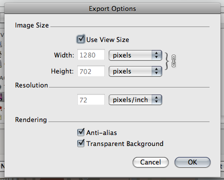
Just a side note: One little surprise when switching to osx, was the fact that sketchup on mac does export tranparency, just remember to export as png, and check the options.
All the other channels (depth and material), can be exported with some ingenuity, though, it´s not a 1 click process
-
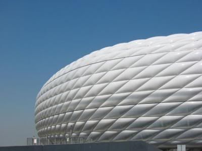
Repetition of a planar shape:(project of H&DM)
repetition of a planar shape: triangle. (project of Toyo Ito)
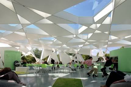
repetition of a 'foldable': (project of H&DM)
Advertisement