Component gluing planes
-
Is there a comprehensive guide to creating components that glue to a specific place in a specific orientation? I have lost, I don't know, 50 hours trying to get some understanding of creating components with gluing planes and I just cannot sort it out.
I had thought I'd read somewhere that SU is smart enough to do this on its own if you create the component in the orientation desired, but that is definitely not the case.
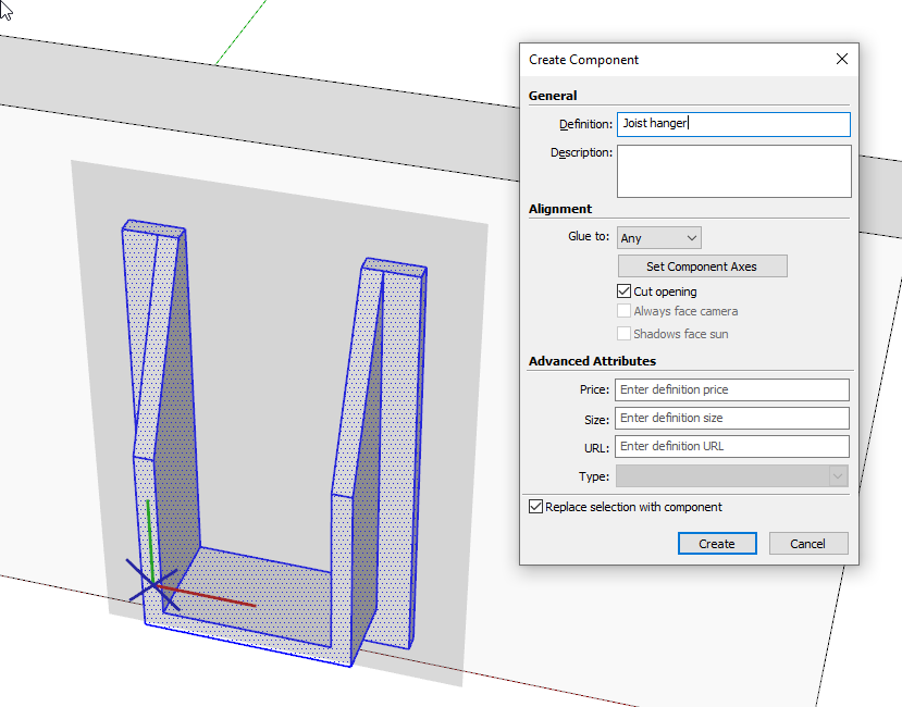
In the image at the link (I also can't figure out how to get correct size and pixels here), I am trying to create this joist hanger such that it glues as oriented at the point indicated. I've been screwing with this for 2 hours now and I'm no closer than when I started.
Does anyone out there understand gluing planes? I bet there is!
Thanks
Bob
https://www.dropbox.com/s/184sffu68h0zdu6/Screenshot%202019-12-01%2007.57.33.png?dl=0
-
This ?
-
Try drawing a rectangle directly on a face inside the beam component, immediately create a component of the rectangle face and edges and set it glue to "any" (it should already be set) set it to cut opening or not as desired. You can then cut the component and paste-in-place outside the beam component. Of course then you can create the hanger or whatever you want within the rectangle component. It will also glue to new surfaces as you import it into the model from the component browser, or use copy and paste from an existing instance.
You can also go to Simpson Strong-Tie in the 3d Warehouse, download a hanger, paste that into your glue-to rectangle component, and re-orient to the axes.
It is also very simple to create the glue-to hanger on the ground plane in a similar method. the hanger would lie flat on it's "back" on the ground plane, but will then be usable to insert from the component browser on any face in the model(s).
Components don't glue to a specific place, but to a specific plane defined by a face.
A gluing component will have the the blue axis look like an "X" in the same plane as the red and green, instead of a line. Where you have a specific orientation and placement point desired--that's where the intersection of the component axes should be.
You can also create a joist/ hanger combined component to place at once. If you are doing materials list that component should contain separate components inside for the board and hanger. Either combined or not, of course, for any run you make one set and move/copy-duplicate along the beam at the correct spacing.
-
The simplest way to look at it is you need to follow the world axes to get your shape to sit the way you want. Easiest way to achieve this is to line it up with the axes and set the component axis to match. Note that the point you select to create the axis will be the insertion point for the component, so Choose wisely.
I modeled this in place then moved it to the ground plane to make it a component.
See how I have clicked to set the red and green to follow the world red and green.
-
FWIW, if you model the component on an ungroupd face is the orientation you need it, when you create the component it will automatically get the gluing property. You can adjust the location of the component's origin and choose which face orientations the component will glue to.
-
Aha! I was trying that on a grouped face. Will give that a try.
Thanks, Dave, as always!
Bob
@dave r said:
ungroupd face
[attachment=0:24aer1fp]<!-- ia0 -->Screenshot - 12_1_2019 , 4_31_42 PM.png<!-- ia0 -->[/attachment:24aer1fp]
-
-
"model in place then move to the ground plane" - that just doesn't make a lot of sense, but hey, if it's what works!
Thanks, Box.
Bob
@box said:
The simplest way to look at it is you need to follow the world axes to get your shape to sit the way you want. Easiest way to achieve this is to line it up with the axes and set the component axis to match. Note that the point you select to create the axis will be the insertion point for the component, so Choose wisely.
I modeled this in place then moved it to the ground plane to make it a component.
See how I have clicked to set the red and green to follow the world red and green. -
Good info here, pbacot. I'll keep at it.
By the way, the official Simpson hardware is so large, file wise, they really bloat a file. They look cool, for sure.
THanks!
Bob
@pbacot said:
Try drawing a rectangle directly on a face inside the beam component, immediately create a component of the rectangle face and edges and set it glue to "any" (it should already be set) set it to cut opening or not as desired. You can then cut the component and paste-in-place outside the beam component. Of course then you can create the hanger or whatever you want within the rectangle component. It will also glue to new surfaces as you import it into the model from the component browser, or use copy and paste from an existing instance.
You can also go to Simpson Strong-Tie in the 3d Warehouse, download a hanger, paste that into your glue-to rectangle component, and re-orient to the axes.
It is also very simple to create the glue-to hanger on the ground plane in a similar method. the hanger would lie flat on it's "back" on the ground plane, but will then be usable to insert from the component browser on any face in the model(s).
Components don't glue to a specific place, but to a specific plane defined by a face.
A gluing component will have the the blue axis look like an "X" in the same plane as the red and green, instead of a line. Where you have a specific orientation and placement point desired--that's where the intersection of the component axes should be.
You can also create a joist/ hanger combined component to place at once. If you are doing materials list that component should contain separate components inside for the board and hanger. Either combined or not, of course, for any run you make one set and move/copy-duplicate along the beam at the correct spacing.
-
I watched that video. For some reason, bolts weren't giving me the problems that I was having with that hanger.
@pilou said:
This ?
-
@bob_cp said:
"model in place then move to the ground plane" - that just doesn't make a lot of sense, but hey, if it's what works!
It was a simple suggestion to help you understand how the axes need to be placed when you are creating them so that you can see what you need to do when creating them in place. But hey...
Hello! It looks like you're interested in this conversation, but you don't have an account yet.
Getting fed up of having to scroll through the same posts each visit? When you register for an account, you'll always come back to exactly where you were before, and choose to be notified of new replies (either via email, or push notification). You'll also be able to save bookmarks and upvote posts to show your appreciation to other community members.
With your input, this post could be even better 💗
Register Login


Advertisement