Foundation Plugin
-
Working on the step tool this evening. This one gets real interesting, lots of possible configurations even though it is a simple linear piece of foundation (ie. Top Step, Bottom Step, Double Step).
I haven't spent too much time looking at the rebar yet for a step but I'm starting to now and just wondering how everyone would like it drawn/configured. I can terminate the rebar lengths at the step or I can extrude them along to follow the path of the step(s). Any thoughts, cad drawings or details showing preferred rebar layout would be extremely helpful.
I have enough tricks in coding toolbox now that I can pretty much make the rebar do anything you want, I just want to make it as realistic as possible without getting overly complicated.
Along that same vein I think I have the other advanced options figured out for a stemwall step: Anchor Bolts, Vents, Insulation. However, I don't know what I want to do with the drain pipe just yet. Obviously it needs to transition from one height to another but what is the preferred way to model this?
-
After some serious head scratching and tossing around various parameters I've managed to boil it down to this:
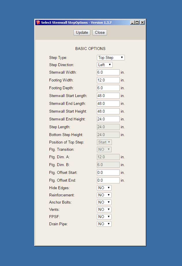
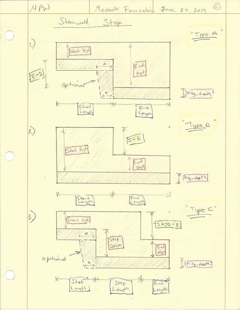
Three different step configurations: Top, Bottom, Double (see previous drawing for details)
The Double Step has three additional parameters as well as the option for the Ftg. transition.
As you can see it gets rather complicated, or at least appears so. In actuality it is fairly simple once you understand what each parameter does.
-
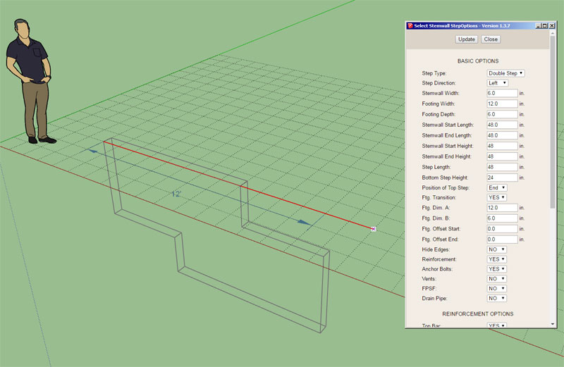
First look at the wireframe preview for a stemwall step:
Tomorrow I start in earnest to code the concrete portion of the module now that all of the supporting infrastructure is in place. Then from there it is rebar, anchor bolts etc...
Hopefully this module combined with the polyline stemwall module will give designers the flexibility they need in order to model any type of stemwall or basement foundation.
-
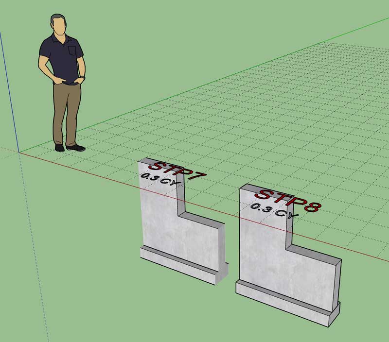
First look at a Type A (Top Step) concrete, with and without hidden edges:
Haven’t really had much feedback with regards to the rebar for a step. For now I think I will just terminate it at the step. We can always talk about lapping and turned up or turned down rebar later as I’m sure the discussion will come up.
-
First look at some bottom steps with 24" steps:
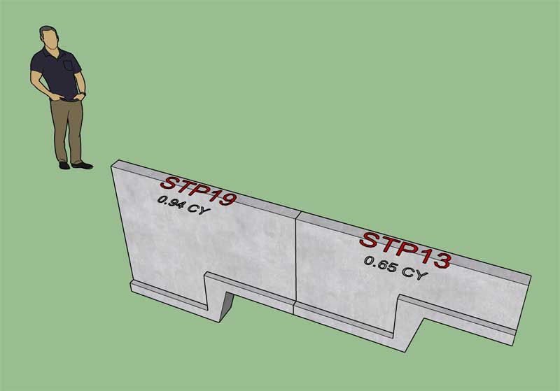
Notice that the optional footing transition has been toggled on.
Now I just need to wrap up the concrete for the double step and then I'll release a new version so that everyone can test out this new feature.
-
Version 1.3.8 - 08.29.2019
- Enabled the "Draw Stemwall Step" tool with the following step types: Top, Bottom, Double.
- Enabled the "Edit Stemwall Step" function/menu for stemwall steps.
- Added a "Hide Edges" option in the draw and edit menus for stemwall steps.
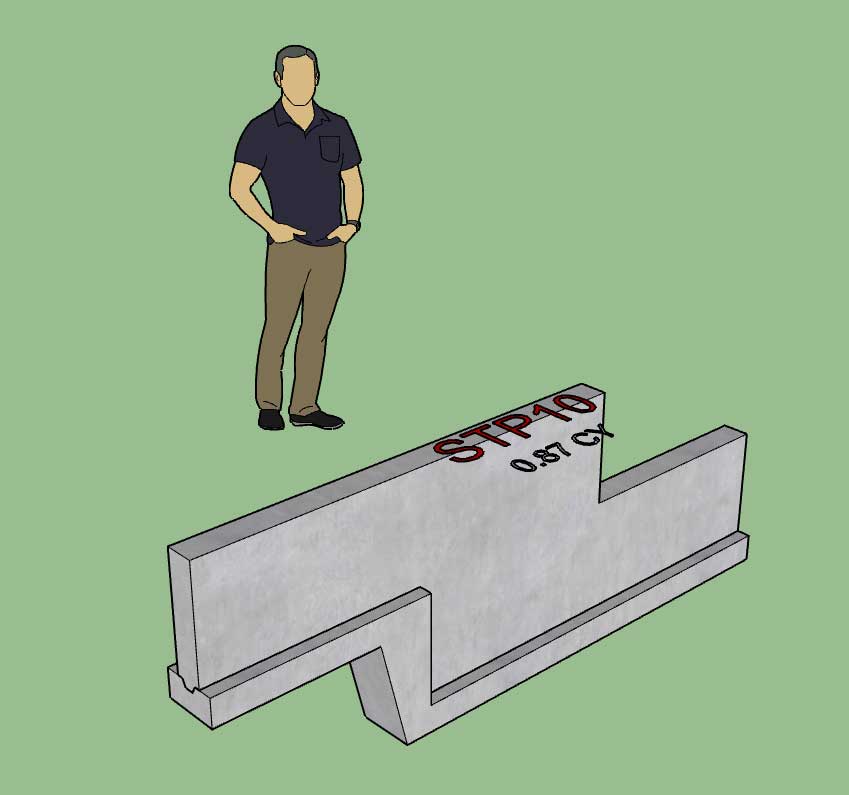
Currently the other options are not yet enabled (anchor bolts, rebar, insulation, vents, and drain pipe). I will work on these this weekend and try to wrap up the stemwall step module by Monday.
After that I will put together the Interior Bearing tool and then move back to the Truss Plugin development for a while. However, if there are specific requests for features or bug fixes I will continue to address those in the next few weeks.
-
This is kind of what I have in mind for the rebar for a top step:
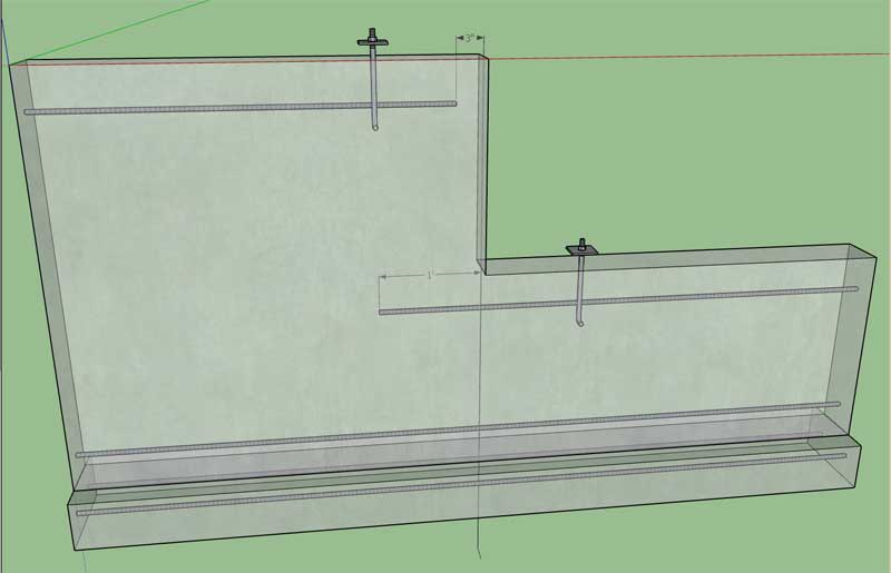
Note the typical 3" clearance for the very top bar. Also note how the other top bar extends beyond the step by 12". I can provide another parameter that allows the user to specify the length of this lap/extension.
I apologize that the dimensions are so small in the image, I should have increased the text size to make it more readable.
The bottom step and double step would be similar. Thoughts or a different rebar configuration?
-
For the drain pipe with a step I'm looking at three possible ways to model the vertical transition:
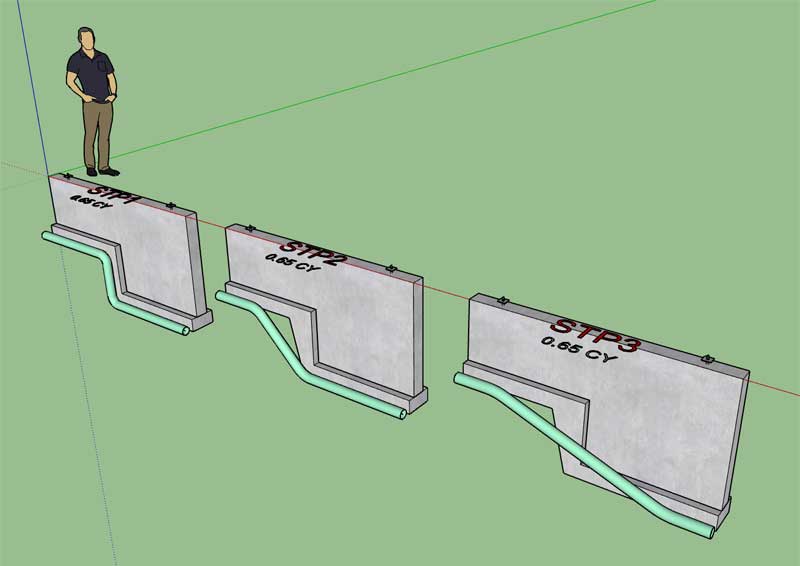
The first model just follows the concrete step and makes a vertical jump.
The second model transitions with a couple of 45 degree elbows.
The third makes a more gradual transition with 16" of lead in before beginning the slope.
Which is the preferred way to model the drain pipe?
-
Version 1.3.9 - 08.30.2019
- Added an option for additional horizontal bars in the draw and edit menus for polyline stemwall foundations.
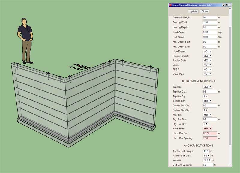
Now we just need a few more options that will allow for vertical bars.
-
Version 1.3.9b - 08.31.2019
- Added an option for vertical bars in the draw and edit menus for polyline stemwall foundations.
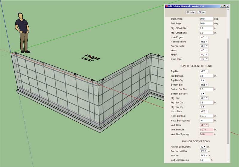
View model here:
3D Warehouse
3D Warehouse is a website of searchable, pre-made 3D models that works seamlessly with SketchUp.
(3dwarehouse.sketchup.com)
The top of the vertical rebar is 3" below the top of the stemwall and extends into the footing by half the footing depth.
These various foundation assemblies are starting to rival the wall and truss plugins assemblies in complexity and details, exciting stuff.
I still need to work on a module that will allow for brick ledges on stemwalls as well as another module for adding in windows and doors. A CMU option would also be nice. No matter how hard I work on this stuff it always seems like there is more, its a moving target I guess.
-
Version 1.3.9c - 09.01.2019
- Enabled rebar for stemwall steps (top step only).
- Added an option for additional horizontal and vertical bars in the draw and edit menus for stemwall steps.
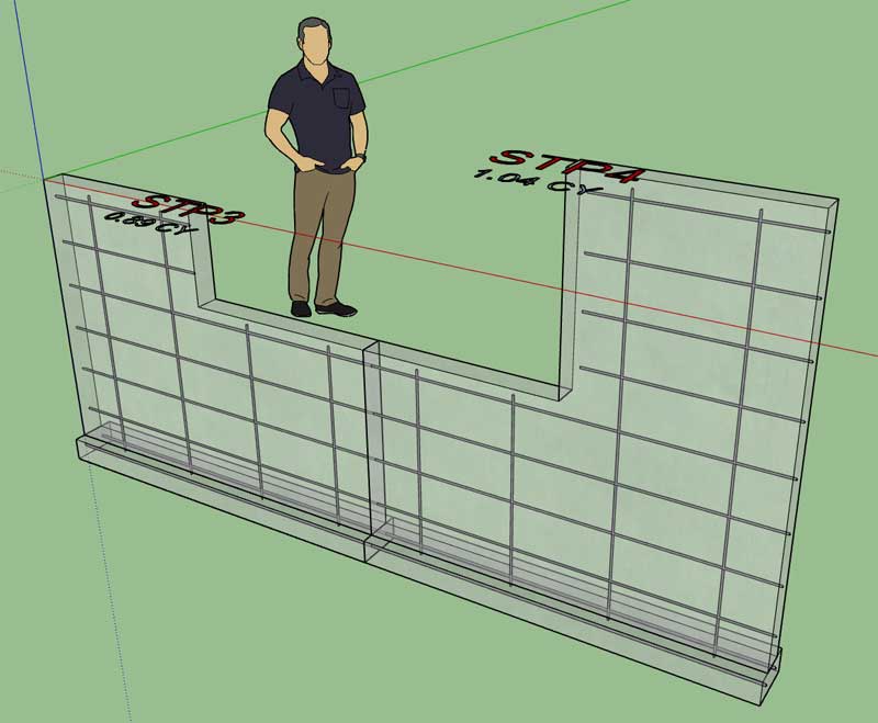
I rolled the revision a little early since I noticed there was a bug in the edit function for stemwall steps. If you've recently installed 1.3.9b, I would highly recommend updating to this latest version.
I just need to work out the rebar for the other two step configurations and then rebar is complete.
I will then attack anchor bolts next, then the drain pipe and then the FPSF insulation. I will probably leave the vents disabled for now or at least until someone gives me more feedback on how they would like to see this configured.
The nice thing with the rebar is that you still have the option to install top and/or bottom bar with or without the horizontal bar, so lots of design permutations.
-
Version 1.3.9d - 09.02.2019
- Enabled rebar for stemwall steps (bottom step and double step).
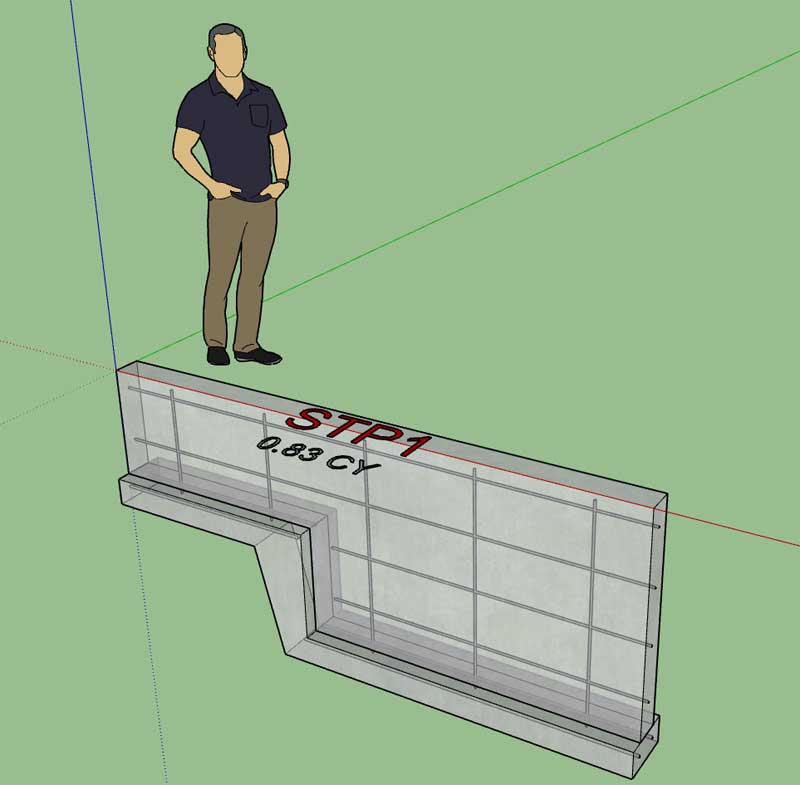
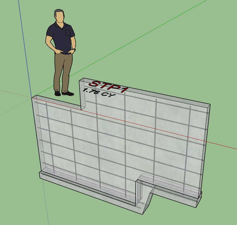
Rebar was a bit a of a pain especially the double step, the rest of the advanced options should be relatively simple comparatively.
-
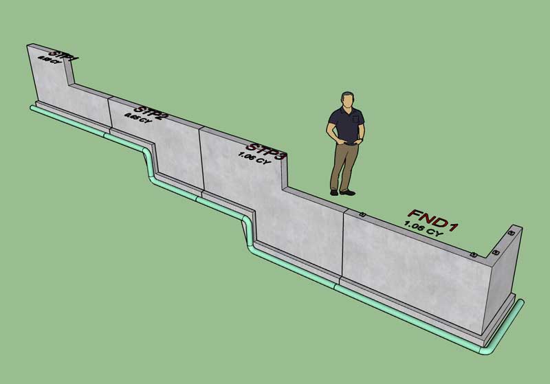
First look at stemwall steps with drain pipe:
View model here:
3D Warehouse
3D Warehouse is a website of searchable, pre-made 3D models that works seamlessly with SketchUp.
(3dwarehouse.sketchup.com)
I don't know why but just looking at this model makes me very happy. I guess I've been trying to do this sort of thing with foundations since I began programming the foundation plugin about three years ago and I am now finally arriving at a viable solution.
Note, that the hide edges option will hide the concrete lines at the end of each assembly and the entire foundation will appear as monolithic. I have not enabled this option in this model because I want to show the three different steps types distinctly.
-
First look at that stemwall steps with FPSF insulation:
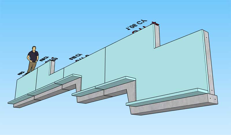
Not sure if an additional piece of insulation should be added at the actual step, any thoughts on that?
View model here:
3D Warehouse
3D Warehouse is a website of searchable, pre-made 3D models that works seamlessly with SketchUp.
(3dwarehouse.sketchup.com)
-
Version 1.4.0 - 09.02.2019
- Enabled drain pipe for stemwall steps.
- Enabled FPSF insulation for stemwall steps.
- Enabled anchor bolts for stemwall steps.
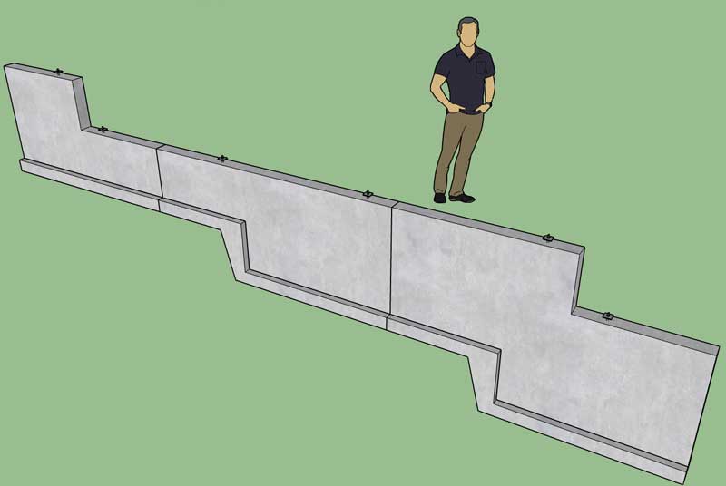
The stemwall step tool is complete.
Again the only thing missing is the vents option (which I have disabled for now). I will give this some more thought and address it as soon as I have a practical solution.
The next item of business is the interior bearing tool/module which will allow for linear interior bearing assemblies (ie. post-and-beam, stud wall, CMU etc...) I'm very familiar with the first two systems however I'm not so familiar with how CMU interior bearings are typically constructed. Any information would be helpful.
This next module is very simple and I hope to complete it within 3-4 days. Then back to the quest for the holy grail of the Truss plugin... Complex Roofs.
-
Parameters for the new Interior Bearing Module:
Basic Options:
Bearing Type: Post and Beam, Stud Wall, CMU
Bearing Height:
Footing Width:
Footing Depth:
Ftg. Offset Start:
Ftg. Offset End:
Sill Plate Offset:
Stemwall Offset:
Rebar Option: Yes/NoPost and Beam Options:
Beam Width:
Beam Depth:
Post Spacing:
Post Width:Stud Wall Options:
Stud Depth:
Stud Width:
Stud Spacing:
Top Plate Qty: 1,2,3
Top Plate Thk.:Rebar Options:
Ftg. Bar Dia.:
Ftg. Bar Qty.:Let me know if I'm missing anything. I haven't included a section for CMU yet since I need to do more research on that particular construction type.
-
Version 1.4.1 - 09.04.2019
- Enabled the "Draw Interior Bearing" tool with the following support types: Post & Beam, Stud Wall.
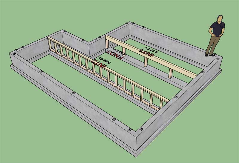
View model here:
3D Warehouse
3D Warehouse is a website of searchable, pre-made 3D models that works seamlessly with SketchUp.
(3dwarehouse.sketchup.com)
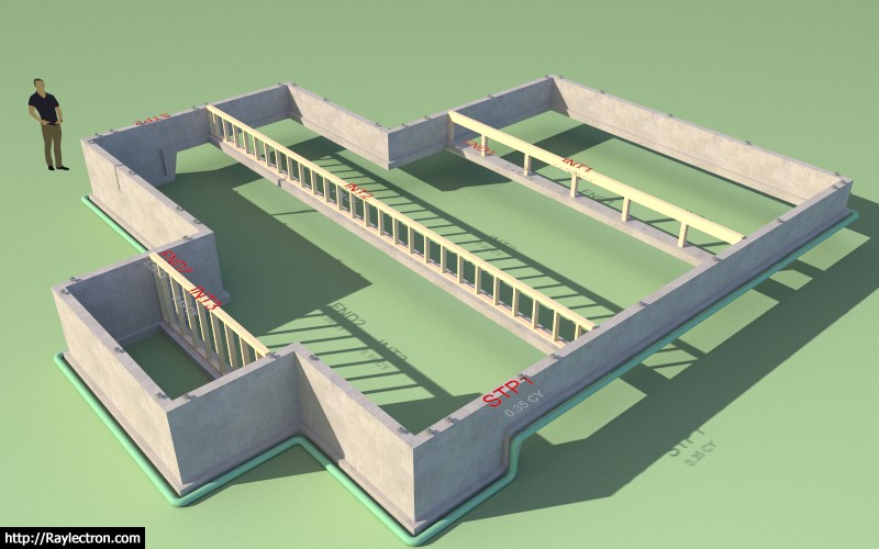
Now a video demonstrating the polyline stemwall, interior bearing and step tool all working together would be interesting.
-
Tutorial 6 - Polyline Stemwalls, Steps and Interior Bearings (13:27 min.):
View model here:
3D Warehouse
3D Warehouse is a website of searchable, pre-made 3D models that works seamlessly with SketchUp.
(3dwarehouse.sketchup.com)
-
There has been some call to provide a CMU option for the polyline stemwall module. In order to represent CMU my intent was to not alter the model but just apply the appropriate material/texture as I am doing with the Wall plugin. However this method only really works with linear sections of walls (at least for the faces parallel to the Z plane):
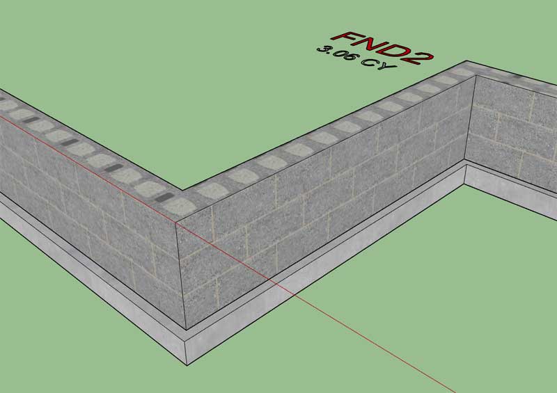
As you can see from the image/model the vertical faces come out just fine however the horizontal faces are a bit of a mess. I really don't want to change up the way I'm modeling the stemwall itself (ie. breaking it into linear segments) so the solution might be to simply provide a more generic material for the horizontal faces without any of the brick interior design, mortar lines etc... thoughts? It would look not quite as realistic when looking at the top of the CMU wall but it also wouldn't appear as confusing as the result shown here.
-
Medeek Live Training: Session 1
Scheduled time is 11:00 PST
This is my first attempt at live streaming so hopefully things go smoothly but I'm sure it will be a bit of a learning experience. The primary topics covered will be the recent additions to the foundation plugin however I am willing to open it up to other questions about all of the other plugins.
Advertisement


