Building basic land survey, points, lines, and dimensions.
-
New to Sketchup but not CAD. We have several very high end softwares but none seem to want to convert to the survey world easily. To be honest, after stepping out of those softwares, Sketchup seems pretty limited but I am hoping I just need to learn more about it. Basically what I am doing is trying to regenerated a couple basic land surveys, then generate extra points in which I can determine their XY position, call them out, or place them on a property line at a defined distance from another point. I am finding this rather difficult. I will try to ask more pointed questions to hopefully get going here.
-
I have 2016 Make on one PC, and 2017 Pro trial on another. I am unsure if the layout features will be more of what I need? I intend to work in 2D right now, but the main focus is the eventually add elevations to all generated points and create a contour map, but that is well down the road. So am I OK using Make for this work or will the Pro tools be more of what I need?
-
Bearing based line generation? Surveys in the USA use quadrant based bearings such as N00'08'12"E 1200ft in which that is 8min12sec angled to the E of true North, with a length of 1200ft.
-
Now, once I am able to generate a basic survey correctly, I need to be able to place field points with coordinate locations, either by placing the point with desired XY values, or by positioning a point at a certain distance from something else such as a property line. I did load point gadget but still seems limited. Are there better tools?
-
Most of my frustration is the lack of adjustablility in the points and dimensions driving the geometry. With point gadget, it certainly will fine a line and put a point on it. But what if I want to move that point? Only way I can find with the mouse. I cannot type the value anywhere and get it to move the point.
-
Also, the point gadget seems to create a polygon around the point in which all the corners are hot too? That seems concerning to get the right one?
-
Dimensions. Typically in other softwares we can simply generate a parallel line, then dimension between those lines and type a value in there to control the line placement to the defined dimension. At this point I cannot even put a dimension between lines, it only wants to look at points?
-
-
@unknownuser said:
- Dimensions. Typically in other softwares we can simply generate a parallel line, then dimension between those lines and type a value in there to control the line placement to the defined dimension. At this point I cannot even put a dimension between lines, it only wants to look at points?
In SU Make (so not in Layout) as shown on your profile
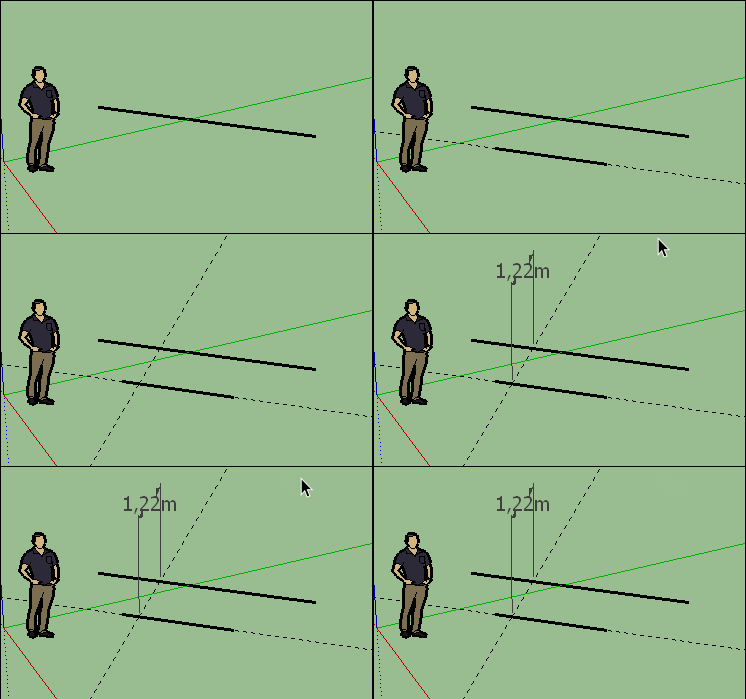
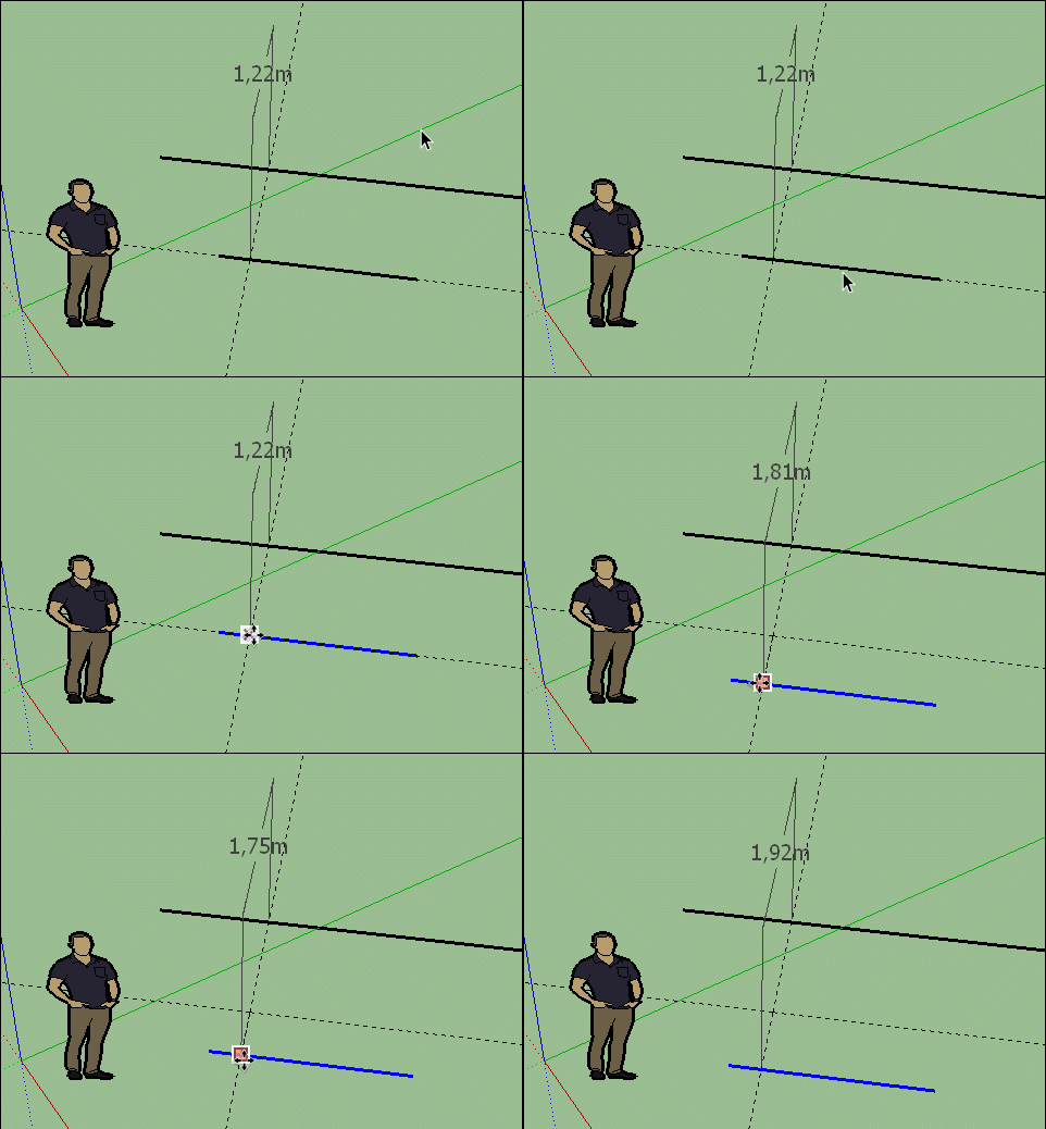
Many strategies are possible if you want dimension out of the "Hot Points"
Use = Draw a line
Use = you have a parallal helper guide line at distance wanted (Click line and )
(just for show how work this tool
because you can simply Copy + line + type dimension for have a parallal)
Use = Draw a second line on the helper guide line
Use = you have a perpendicular anywhere on the lines (or no perpendicular)
Use = you can now dimension at intersections between Lines , Helper lines!

You can now move the lines along perpendicular if you want another distances!


-
SU can appear basic especially compared to a dedicated civil setup however it's a bit of a swiss army knife and can be surprisingly versatile.
With regards positioning points you can move/copy objects/guide points using absolute/relative coordinates.
Just begin the move/copy process and type the coordinates as [x,y,z] for absolute or <x,y,z> for relative. Bear in mind that the reference point is the point where the original object is selected.
-
Or [x;y;z] and <x;y;z> depending how set your "decimal point" on your Operating System!

-
@fastline1 said:
Sketchup seems pretty limited but I am hoping I just need to learn more about it.
SketchUp looks 'limited' intentionally, you enhance it according to your needs with plugins. So you're not dealing with unnecessary features & buttons that you'll never use all over the place.@fastline1 said:
- So am I OK using Make for this work or will the Pro tools be more of what I need?
If you're making profit, you must get Pro licence regardless of tools. https://www.sketchup.com/license/b/sketchup-make (check use of products section)
@fastline1 said:
- Bearing based line generation? Surveys in the USA use quadrant based bearings such as N00'08'12"E 1200ft in which that is 8min12sec angled to the E of true North, with a length of 1200ft.
I haven't try but this plugin might be useful: 2DXY SiteSurvey tools
@fastline1 said:
- placing the point with desired XY values, or by positioning a point at a certain distance from something else such as a property line. I did load point gadget but still seems limited. Are there better tools?
@fastline1 said:
- But what if I want to move that point? Only way I can find with the mouse. I cannot type the value anywhere and get it to move the point.
With Point Gadget plugin you can export .csv file and adjust numbers precisely (or even add new points) in Notepad++, then import again. There is also this plugin if you're interested: Coords-Tag from Datum
@fastline1 said:
- Also, the point gadget seems to create a polygon around the point in which all the corners are hot too? That seems concerning to get the right one?
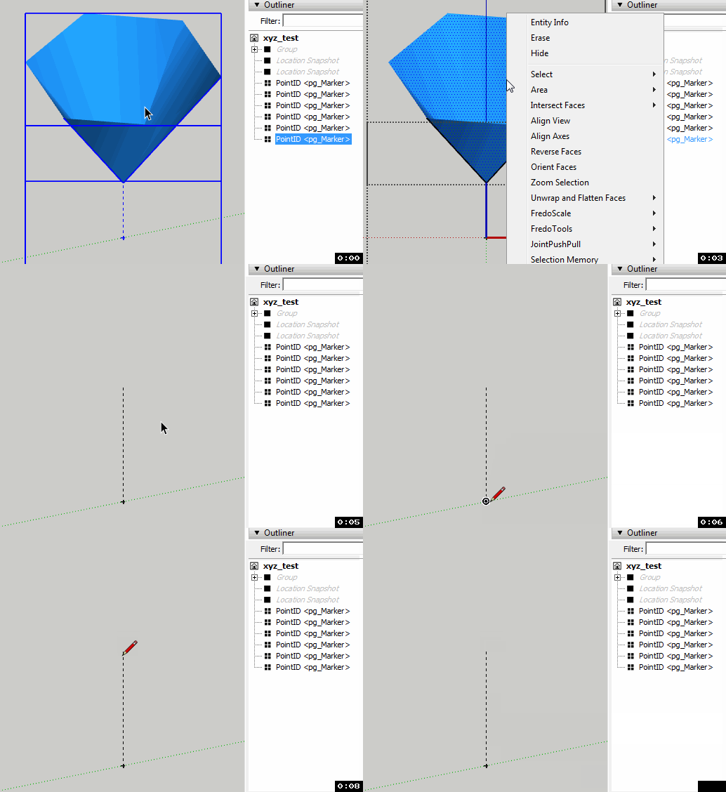
Simply double click one of your points > right click to face > hide (notice its edges are hidden already). Because it's a component, all other cones will be hidden as well.

- So am I OK using Make for this work or will the Pro tools be more of what I need?
-
Sorry, I did not see new replies before posting. Thank you! I may give this a shot. No, this is not paid work. This is my own place and I am simply trying to establish point markers in the field with a total station to identify things such as pipes and wires in the field so I can always find them again. Basically all I need to to is recreate my survey dimensions, then create my own origin system. Then I can go back to it any time.
I decided to use my property pins to help establish my system, then add more points to fix my location as this is standard survey practice to improve accuracy of location.
Questions I have for now.
-
I have been able to generate points and as mentioned above, hid the cones on the points, which should work well. But can I put the cones in a layer I can turn back on for a better visual when needed? Can I modify the color of the cones? Create a key for the colors so I know what each is? Also, and probably the biggest, is there a way to edit the name of the point later? The tool prompts for a name but then I cannot edit that. Probably a way?
-
Angles. It looks like the system wants me to just move a line until the parameter value shows the angle I want. I am used to throwing a line, then dimension it, then edit the dimension and the line move where I want it and it locked by that dimension. We call it constraining. Is there a way to add at least an angle dimension for reference? Always good to see a visual of the angles.
-
-
Also
-
Line creation. In my previous post (that will show up hours from now, lol), I am trying to create parallel lines with certain distance from their parent line. I can see if I grab the tape measure tool, click the parent line, it will generate a parallel reference but can I somehow enter a value at that point? I am just moving my mouse around hunting the for right value.
-
As well with lines. It appears what I need to do is generate lines by first creating reference lines, then I want to extend those line to a defined length. What I am doing is creating a line, then adding a dimension, then using the move tool to move the end point and I can see the dimension move but is there not a way to type in the dimension value at that point instead of trying to get the mouse to the right point?
-
-
Also, lets assume that I want to move a line or other geometry in the Z by a defined value? I can see that I can grab a line and move it, but where would I enter the value that I want?
-
@fastline1 said:
- But can I put the cones in a layer I can turn back on for a better visual when needed? Can I modify the color of the cones? Create a key for the colors so I know what each is? Also, and probably the biggest, is there a way to edit the name of the point later? The tool prompts for a name but then I cannot edit that. Probably a way?
Yes you can, treat those points like any other geometry. Check this help article: Using Layers and check this plugin: Layers Panel. You can change names via 'entity info' or 'outliner' under 'default tray'.
Also check this: Adding Colors and Textures with Materials. Try to search future issues there, you may find detailed info.
@fastline1 said:
- Is there a way to add at least an angle dimension for reference? Always good to see a visual of the angles.
Did you try 'protractor' tool?
@fastline1 said:
- I am trying to create parallel lines with certain distance from their parent line. I can see if I grab the tape measure tool, click the parent line, it will generate a parallel reference but can I somehow enter a value at that point? I am just moving my mouse around hunting the for right value.
@fastline1 said:
- As well with lines. It appears what I need to do is generate lines by first creating reference lines, then I want to extend those line to a defined length. What I am doing is creating a line, then adding a dimension, then using the move tool to move the end point and I can see the dimension move but is there not a way to type in the dimension value at that point instead of trying to get the mouse to the right point?
@fastline1 said:
I want to move a line or other geometry in the Z by a defined value?
Yes, pick move tool > select your object > type your length > hit enter. See measurement box left below (by default). You can lock your x,y,z axis with arrow keys. - But can I put the cones in a layer I can turn back on for a better visual when needed? Can I modify the color of the cones? Create a key for the colors so I know what each is? Also, and probably the biggest, is there a way to edit the name of the point later? The tool prompts for a name but then I cannot edit that. Probably a way?
-
For what it's worth, I normally work up my survey data [total station] in CAD [draftsight] as far as possible before importing the dwg drawings to SU. For example, i may setup 2D Plans/Elevations etc along with 3D data like spot heights. I just use the raw nodes points as markers which import as guide points but you could create blocks for your markers.
The main issue is that the text is lost although there are ways around this if you really need it. Another tip is to import and arrange scaled JPGs of the CAD drawings as a visual reference.
If this type of workflow would suit you and you want to continue to work on the base survey data you can also XREF the Survey drawing using TIGs plugin.
Advertisement


