Ways to lock "Retc.on surface" to a pre-determined axis?
-
This is tricky to explain, but I think you are missing the point.
Drawing aligned to a specific axis works in SketchUp 2015, but not on a specific plane. I want to draw a rotated rectangle (meaning, the red and green axis is ignored, but the blue axis is not) which ends up horizontally flat even though the terrain below isn't flat. If I wanted to just lock to the red and green axis I would use normal rectangle tool. -
@intelcoreduo said:
....... I want to draw a rotated rectangle (meaning, the red and green axis is ignored, but the blue axis is not) which ends up horizontally flat even though the terrain below isn't flat. ....
Yes, that's what I did.
What if you position the tool where the first corner needs to be, not click -> releasing the mouse button yet, but click -> hold the mouse button down. Drag the cursor up till you see the protractor turning blue. Only then release the button. So you have your first corner located right and the first rectangle edge is going to be horizontal, whichever direction you draw it.
Try taking it from there and see if you can manage to also get the second edge (perpendicular to the first) in he same horizontal plane. I've done it. -
Just ignoring the easiest way? Place a pre-made component and make unique. Why draw a rectangle? You can even place a cube, rotate, then push-pull or scale to size. Sounds like you are asking your colleagues to watch a tedious method for no purpose.
But the discussion is good to learn drawing and inference methods.
-
Hi folks.
Click in sequence on the scenes tabs of this SU file for another method.
-
@jean lemire said:
... Click in sequence on the scenes tabs of this SU file for another method.
Hi Jean, I see only one scene tab when downloading > opening your file. Did you upload the correct example file? Just curious.
-
Hi Gerrit, hi folks.
Yes, wrong file, sorry. I corrected it.
Best regards.
-
@pbacot said:
Just ignoring the easiest way? Place a pre-made component and make unique. Why draw a rectangle? You can even place a cube, rotate, then push-pull or scale to size. Sounds like you are asking your colleagues to watch a tedious method for no purpose.
But the discussion is good to learn drawing and inference methods.
This method does work, but is slightly more steps than the rotated rectangle method should have have, especially when you have a large variation in required shapes (slightly more tedious to place correctly or resize of the box is way too large or way too small)
A) Copy box
B) paste box somewhere nearby
C) Click on a reference point on box, such as lower corner
D) Click on part of terrain where I want my lower corner
E) Rotate, (shift to lock on blue plane) and click on correct corner rotate
F) Click a second time to get rotation right
G) Resize Z axis
H) Resize X axis
I) Resize Y axisWhich is pretty quick, but not as quick as the 5 steps using rotated rectangle (or at least how quick it would be if step D was easier)
-
@jean lemire said:
Hi folks.
Click in sequence on the scenes tabs of this SU file for another method.
I can't destroy the terrain as I need to show several alternatives and might have to slightly alter the buildings later. They need to be in independent groups. I could extrude and group the objects then drop the groups down onto the terrain. But this method requires a few more steps than rotated rectangle directly on terrain, including creating/deleting the above plane, and dropping down (which is pretty quick with the Drop Groups plugin).
It also means switching views/perspective a lot, which is what I'm trying to avoid. -
@box said:
Use the Up arrow to lock the starting point to the blue axis, click and release, move to the angle you want, click and release to set the first edge, move the mouse and watch for the blue inference, click to finish.
This is brilliant, but it only works because the terrain in your animation is so tiny. In the last step, you snap to the red axis on the protractor. If the terrain continued behind, the tool would insist on snapping to the terrain mesh triangles instead (at least if the mesh is high resolution)
How did you make an animated screenshot, btw?
-
hi guys, thanks a lot.
This is to avoid any more confusion:
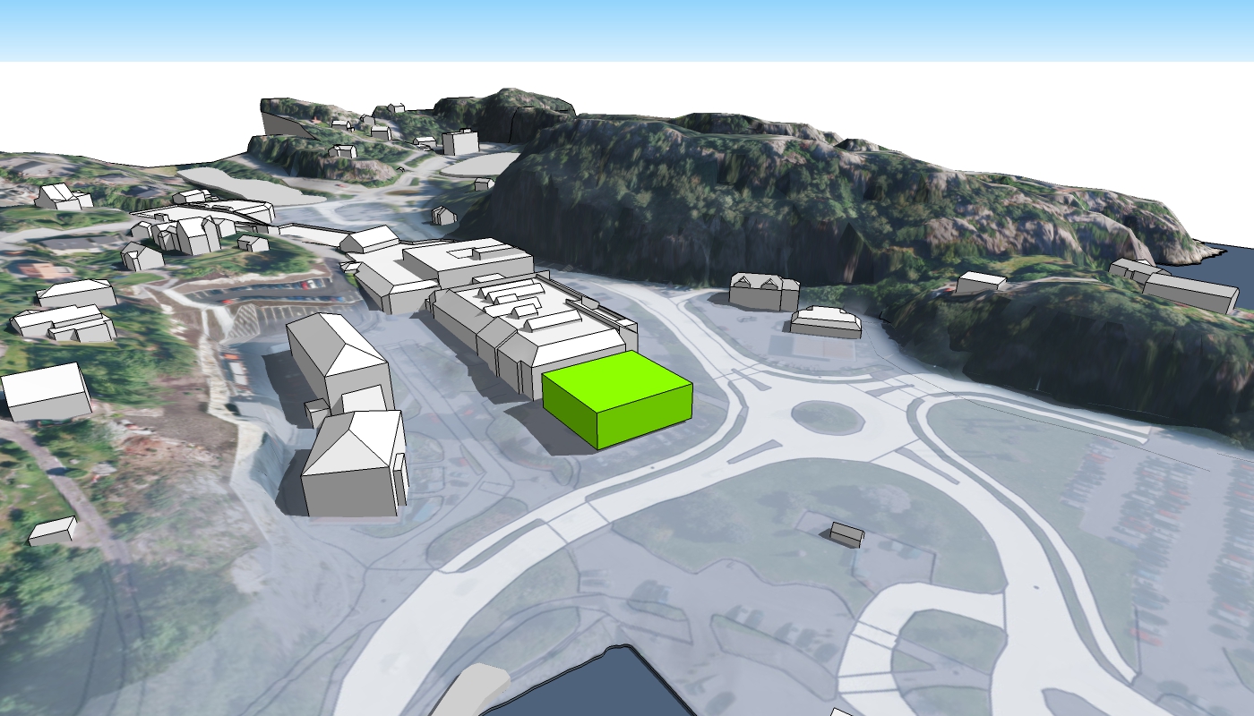
I should like to create the green box (image 1) with a few clicks/little effort/quickly as possible. This should not interfere with the terrain group, as I will probably move some of the buildings at a later point, or create several alternatives in various layers.
From reading this thread, the easiest method (fewest steps) I can find is the following:
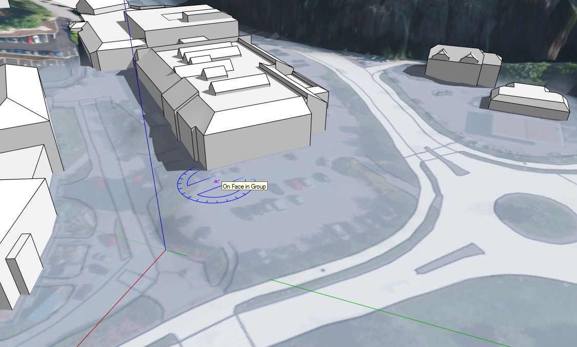
A) Press up arrow to make the protractor blue
B) Place the first point (image 2)
C) Place the second point (to determine building rotation and width)
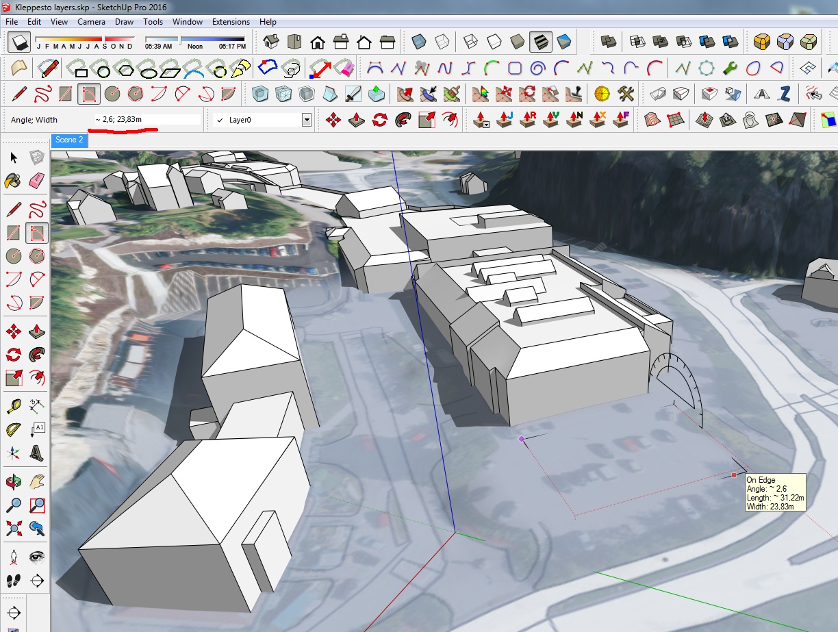
D) Place the third point* (to determine building length) (image 3)
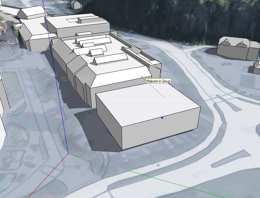
E) Extrude to the same height as the other building (image 4)This is easily the quickest method I can think of as each data point only demands one click, except one problem with step D (image 3).
- When I click to make the third point it will snap to the terrain, and make the building tilted.
Instead of clicking for the third point, I can read off the dimensions (image 3, upper left corner) and then type in: 0;24 where it says 2,6 ; 23,83 (which means Angle ; distance)
If I could snap to the red axis on the protractor in step D, this would probably be the easiest way possible - no need to create horizontal planes, no need to move objects down to the correct height, no need to switch views/perspectives and the whole process would take about 4 seconds - which is important as I do this process a lot.


- When I click to make the third point it will snap to the terrain, and make the building tilted.
-
Hi folks.
See added scene 4 in this SU file for an idea that doesn't affect the terrain since it is a separate group.
Any of the blocks can be made as a component or group and then manipulated as you wish by moving or rotating. You can use the Push/Pull tool to modify the dimensions of each making it shorter/longer or narrower/wider.
Advertisement


