Intersect_with revisited
-
@slbaumgartner said:
@sdmitch said:
The red faces are faces that consist of two or more grid "cells".
I'm not sure what you mean by this. Do you mean that the intersection produces duplicate Faces?
No not duplicate faces but what should be two or more faces somehow combined into one face.
-
What technique are you using to identify the red faces? They look pretty regularly sized, so I am confused about what the floor grid looked like...were its cells of varying size?
I've not seen that effect, but it looks like it is sensitive to the exact geometry involved and its location in model coordinates. Maybe there are "leaks", i.e. Faces not quite closed because of where the intersection points were placed? That could be a consequence of finite computer arithmetic during the intersection. Those look like roof planes, and if so this is probably not the infamous nearby vertices behavior. Maybe you could examine a sample closely to see?
-
@slbaumgartner said:
What technique are you using to identify the red faces? They look pretty regularly sized, so I am confused about what the floor grid looked like...were its cells of varying size?
I've not seen that effect, but it looks like it is sensitive to the exact geometry involved and its location in model coordinates. Maybe there are "leaks", i.e. Faces not quite closed because of where the intersection points were placed? That could be a consequence of finite computer arithmetic during the intersection. Those look like roof planes, and if so this is probably not the infamous nearby vertices behavior. Maybe you could examine a sample closely to see?
I compared the area of the face to what the area of a full "cell" would be and colored red any faces that exceeded the limit. In this case the grid is 1m X 1m.
I would agree that there might be faces not closed if the results was the same each time but, as you can see, that is not the case.
Here is an example of what should be three faces combined into one.
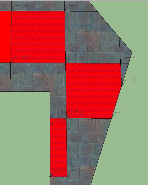
and the coordinates of the vertices- Point3d(3571.39, 1044.32, 154.416), 1. Point3d(3571.39, 1043.97, 154.137), 1. Point3d(3582.77, 1043.97, 154.137), 1. Point3d(3582.77, 1074.56, 178.92), 1. Point3d(3614.04, 1074.56, 178.92), 1. Point3d(3622.14, 1092.34, 193.32), 1. Point3d(3622.14, 1105.15, 203.702), 1. Point3d(3582.77, 1105.15, 203.702), 1. Point3d(3582.77, 1135.75, 228.485), 1. Point3d(3543.4, 1135.75, 228.485), 1. Point3d(3543.4, 1105.15, 203.702), 1. Point3d(3582.77, 1105.15, 203.702), 1. Point3d(3582.77, 1074.56, 178.92), 1. Point3d(3571.39, 1074.56, 178.92), 1. Point3d(3571.39, 1070.32, 175.479)
-
Most intriguing! I don't have an answer, but here's some more discussion for thought...
At least to the precision you printed out, points 4 and 13 are identical, as are points 8 and 12, yet these vertices have not been merged. That is probably the cause of the behavior: the sequence of vertices looks like an ordinary outer loop to SketchUp. But why are they separate? And why did SketchUp gather them into a Face? Possibilities that come to mind:
- they differ in decimal places beyond what you printed but still larger than the merge vertices threshold of 0.001". I don't know what units you used, so can't tell. At full precision, there might be a tiny gap between these points.
- the merge vertices and geometry cleanup operation misfired (which would be a bug!)
- the intersect operation explicitly built these Faces that way (which would also be a bug!)
Regarding the randomness, do you get different results if you undo the operation and then redo it with the identical geometry? If this produces the same results but moving or changing the geometry in any way causes different results, it sounds like a computer arithmetic problem that varies depending on the exact values encountered (not that this observation gives you a clue what to do about it
 .
.One trick I've had work in some situations is to nest everything one extra level deep in a Group, do the work, and then explode that temporary Group when completed. This seems to trigger another round of geometry cleanup which may repair the flaws.
-
If you are likely to get faces with 'twisted vertices', e.g. forming 'bow-ties' or in your case worse...
Then I suggests the following...
Collect the vertices' points into an array.
Get a face normal vector from one of the faces -vec=face.normal
Add a temporary group into those faces' context.
Iterate the collected vertices' points.
For each point, add short 'vertical' edge to thetemp_group.entities...
Collecting the new edges as you go...
Initiallytedges=[]
then iterating...
tedges << ents.add_line(point, point.offset(vec))
When done, explode the group to try and split the 'bow-tie' faces.
Finally erase thetedges- testing for validity...
temp_group.explode tedges.each{|e| e.erase! if e.valid? }
If those faces which need to get fixed are 'coplanar', then there is no risk of the newtedgesgeometry clashing with some existing geometry, so the validity check is academic...

-
@slbaumgartner said:
Most intriguing! I don't have an answer, but here's some more discussion for thought...
At least to the precision you printed out, points 4 and 13 are identical, as are points 8 and 12, yet these vertices have not been merged. That is probably the cause of the behavior: the sequence of vertices looks like an ordinary outer loop to SketchUp. But why are they separate? And why did SketchUp gather them into a Face? Possibilities that come to mind:
- they differ in decimal places beyond what you printed but still larger than the merge vertices threshold of 0.001". I don't know what units you used, so can't tell. At full precision, there might be a tiny gap between these points.
- the merge vertices and geometry cleanup operation misfired (which would be a bug!)
- the intersect operation explicitly built these Faces that way (which would also be a bug!)
Regarding the randomness, do you get different results if you undo the operation and then redo it with the identical geometry? If this produces the same results but moving or changing the geometry in any way causes different results, it sounds like a computer arithmetic problem that varies depending on the exact values encountered (not that this observation gives you a clue what to do about it
.One trick I've had work in some situations is to nest everything one extra level deep in a Group, do the work, and then explode that temporary Group when completed. This seems to trigger another round of geometry cleanup which may repair the flaws.
I have set the precision to the max and that doesn't solve the problem. I have undone and redone with different results. I thought about the multi-level group and created three levels worth that may have lessened but didn't eliminate the problem.
There definitely seems to be a problem somewhere in the way sketchup integrates the edges created by the intersect into the model.
-
@sdmitch said:
Anyone else seen this
Yes, I've encountered this as well and have had some success with the following method. Instead of exploding the intersection edges into the face group with one explosion, the edges are distributed randomly over something like 20 groups, and these are then exploded into the face group. On complex geometry this is both faster and more robust, for some unknown reason.
I've added a small file and a code snippet to illustrate the principle. Select the two groups and run the script.
mod = Sketchup.active_model # Open model
ent = mod.entities # All entities in model
sel = mod.selection # Current selection

gs = sel.grep(Sketchup;;Group)

#find the edge group
eg = gs.select{|g| g.entities.grep(Sketchup;;Face).length == 0}[0]
#find the face group
fg = gs.select{|g| g.entities.grep(Sketchup;;Face).length != 0}[0]

#collect all edges from the edge group
es = eg.entities.grep(Sketchup;;Edge)
#compute a tranformation from the edge group into the face group
tr = eg.transformation * fg.transformation.inverse

#create #no_of_groups empty groups in the face group
no_of_groups = 20
ess = []
(1..no_of_groups).each { |i| ess << fg.entities.add_group }

#add edges more or less randomly to the groups
i = 0
es.each { |e|
  ess[i % no_of_groups].entities.add_line(e.start.position.transform(tr), e.end.position.transform(tr))
  i += 1
}

#explode all groups
ess.each { |g| g.explode }

#delete the edge group
eg.erase!
-
Thanks Caul for your input. Although I wasn't able to use your model since I'm stuck in 2014, I was able to use the code in a model of my own. Even using your technique, the number of groups created is critical. In my tests, 20 groups gave desired results but, when I reduced the number to 10, I got the same results that I had been getting with multiple faces combined into one.
-
@sdmitch said:
Thanks Caul for your input. Although I wasn't able to use your model since I'm stuck in 2014, I was able to use the code in a model of my own. Even using your technique, the number of groups created is critical. In my tests, 20 groups gave desired results but, when I reduced the number to 10, I got the same results that I had been getting with multiple faces combined into one.
After toying around with this a little bit on very complex grids I think that the most robust approach is to use only two sub groups. One with horizontal edges and the other with vertical edges. This seems to solve almost all cases...
-
Perhaps but then you have the added burden of figuring out what is horizontal and what is vertical. Creating a group for each edge seems to work every time and does so fairly quickly.
-
@tig said:
If you are likely to get faces with 'twisted vertices', e.g. forming 'bow-ties' or in your case worse...
Then I suggests the following...
Collect the vertices' points into an array.
Get a face normal vector from one of the faces -vec=face.normal
Add a temporary group into those faces' context.
Iterate the collected vertices' points.
For each point, add short 'vertical' edge to thetemp_group.entities...
Collecting the new edges as you go...
Initiallytedges=[]
then iterating...
tedges << ents.add_line(point, point.offset(vec))
When done, explode the group to try and split the 'bow-tie' faces.
Finally erase thetedges- testing for validity...
temp_group.explode tedges.each{|e| e.erase! if e.valid? }
If those faces which need to get fixed are 'coplanar', then there is no risk of the newtedgesgeometry clashing with some existing geometry, so the validity check is academic...
I had come up with a similar process to deal with the "bow ties" by finding the faces that were to big, saving the edges, deleting the face, and finally doing a .find_edges for each of the edges. This seemed to work in most cases but would obviously fail if the faces were "cell" fragments.
-
@sdmitch said:
Perhaps but then you have the added burden of figuring out what is horizontal and what is vertical. Creating a group for each edge seems to work every time and does so fairly quickly.
The trouble is that
entities.add_groupbecomes very slow after a while. Nevertheless, I've attached my final version. It divides the edges into classes based on orientation, and these classes are then further divided into groups of max 250 edges. All examples seems to merge correctly. There is also some verification built into the code.I encountered this problem in flowify where the (extended) projection grid intersects the geometry and even though distributing the edges over many groups alliviated the problem it did not fully solve it, so I'm quite happy to have found a better way.
As a general observation, intersection is really two distinct problems, the first is to find the intersection edges and the second is to merge the geometry. My biggest problem with intersect stems from the first part. A face in Sketchup does only have to be almost flat while the intersection between two faces is computed from two exactly flat mathematical planes. This means that the intersection edges may fail to merge with the not-exactly-flat face due to tolerance issues. I've found that the following procedure produces a more robust intersect, especially for complicated surfaces:
1) Transform the geometry to a gigantic scale
2) Check all faces by computing a plane form the vertices and then check that all vertices are on that plane. If they are not, then triangulate the face.
3) Intersect
Hello! It looks like you're interested in this conversation, but you don't have an account yet.
Getting fed up of having to scroll through the same posts each visit? When you register for an account, you'll always come back to exactly where you were before, and choose to be notified of new replies (either via email, or push notification). You'll also be able to save bookmarks and upvote posts to show your appreciation to other community members.
With your input, this post could be even better 💗
Register Login


Advertisement