Dynamic component box
-
Hi,
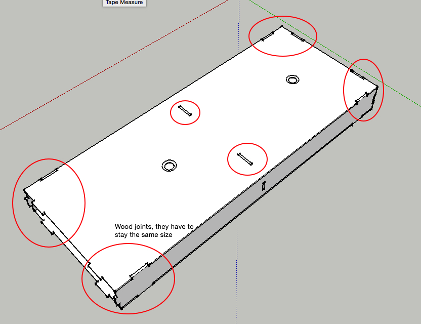
i want to make a dynamic component of a wooden box that contains different wood joints. I want to make the box dynamic and the wood joint must stay the same size every time i adjust the size of the box.
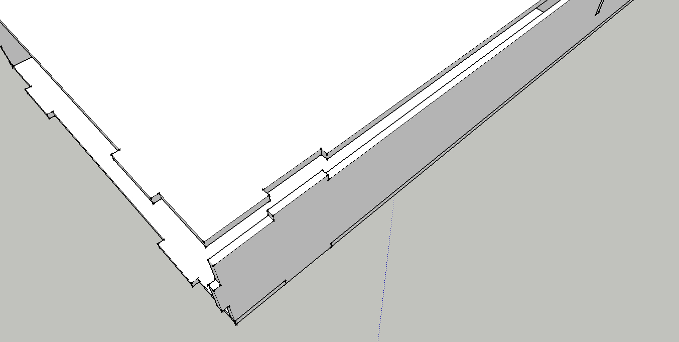
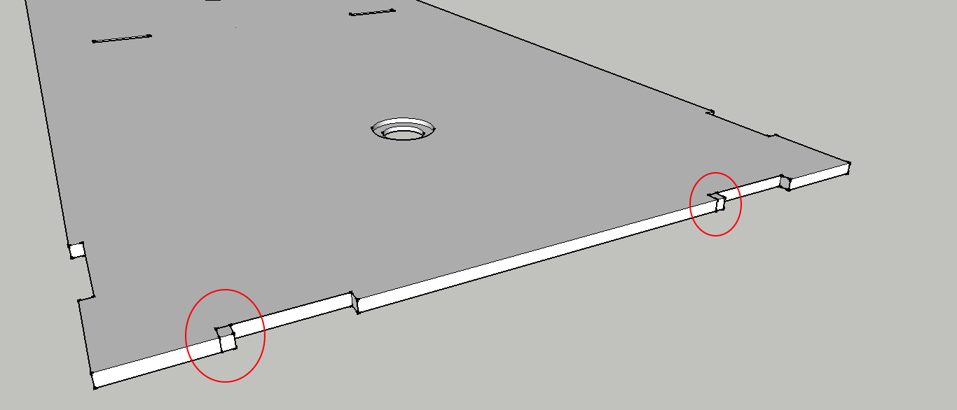
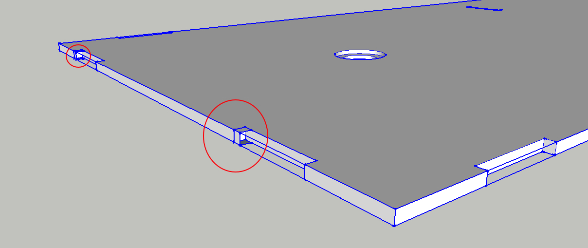
The problem is when i use the scale tool, the wood joints also scale with it. So i used the = in component attributes to lock the sizes of the wood joints. But when i adjust the size, i have a problem with the joints, they resized but the joint is not good, it looks like sketchup add more components. I attached the .skp and screenshots.
Can someone point me in the right direction?
-
The basic answer is that you haven't told the holes what size to be via the DC attributes dialog box. If you don't lock is a size (either a integer or with a formula) the hole will always change size when scaled.
I'm working on something to better explain it to you. Holes like you have drawn are a little tricky to do with DC.
-
@denbost said:
Holes like you have drawn are a little tricky to do with DC.
Yes the trick is to only add stuff, never to remove stuff.
So what you should do is to create a board that is smaller (size of the box without joints) and then add outside volumes to make the positive part of the joints.
You add the surrounding stuff and leave the holes out.
The very difficult part is that you have to size everything relatively to the box so it fits in the rigth place... always.
You should also hide the connection faces and edges between box and "positives of holes"
-
As previous said, you divide the object into parts and build the relationship between them. A reasonable time consuming effort. So first one must ask whether its worth it. If you going to create say 5 to 10, I would say not...20 to 100 yes.
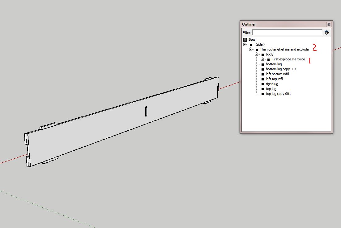
Then decide what avenue to take in regards to its use, technically or aestheticallyA method that I currently employ is to create a DC that I can change back to a solid. The DC in the file attached is of one side of the box. Right click it and save it to a designated folder as a component. Now you can change its options to size required, Then by using outliner and expanding the contents you can see two points, one where the hole / slot can be exploded twice, then another where it can be outer-shelled and exploded. These operations can be done by right clicking (context menu) and selecting the appropriate action within Out-Liner. This creates a solid side with just the front wrapper. If you require to change it then swap it for the saved component (it will update to current option selections as it still retains the cover component)
The benefits of such approach is that one achieves smaller file sizes, protects ones intellectual rights and "Dave can take it off in Cut List"The side lugs were done using the normal make a part and build relationship
the top and bottom done using a copy methodWhen I built the slot or hole, I selected a rectangle on the body surface then applied a cut face when making it a component. Next enter the component, push-pull to create sides then delete the front & back surfaces. Exit then created a matching rectangle component with a cutting plane at rear, deleted the surface then moved it into position. Thus creating a movable hole components, these named "front and "back" are the first to be exploded to make a solid body with a hole in when changing the DC to a standard component.
It took me 3 hours to create this side, so probably a full days work to make a the box...you need always to consider if a DC is worth it (plus half an hour to write and edit this)
Hello! It looks like you're interested in this conversation, but you don't have an account yet.
Getting fed up of having to scroll through the same posts each visit? When you register for an account, you'll always come back to exactly where you were before, and choose to be notified of new replies (either via email, or push notification). You'll also be able to save bookmarks and upvote posts to show your appreciation to other community members.
With your input, this post could be even better 💗
Register Login


Advertisement