Issue rotating to fit
-
You can set the rotation orientation by moving the cursor over the ground plane, towards the green or red directions, or over a face. You can even set it to a line (by another technique). You lock the rotation orientation by holding down the shift key (but you can then still move to the axis of rotation position).
-
If this building stays symmetrical, you can do a lot of work by making a component that is half the width of the building, and mirror that. Later you can explode the overall component to have unsymmetrical editing.
I should add that moving the skylights to the far end of the building won't work because that end is built differently. If they were to be the same, using mirrored components or mirror / copying the earlier work would make it easier. I suspect you did this rather than build each end from scratch, but something happened.
-
Your skylight fits I think. The crossing gable lines of the roof are not square to the axis, though the central line is (not a 90 deg at the peak). I would mirror the skylight: copy the skylight then "edit / paste in place". You then have a copy in the same location. Select "scale" then scale by the center side button moving towards the blank space. move till it pops into -1.00.
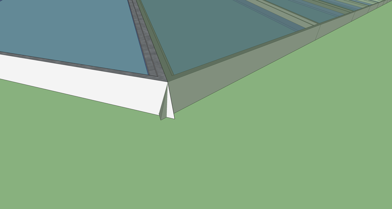
Now it will look like the skylights are not fitting, but you can move the new skyight(at the peak) and snap it to the old. Looks OK to me. Problem is the joint of the skylight is not a vertical plane. That is why scaling did not place it exactly. The skylights overlap where they should meet in a vertical joint.
See picture"Flip / along red direction" also seems to work OK
-
I have used the arrow keys to lock line orientation, but never thought of using it for rotation. move along the ground plane? does that mean under the object? Only know to click somewhere on the object, then a second point, then start rotating. I made the box to be sure the second point wasn't sliding down the face, couldn't get it right.
I did copy the other side, but i did feel something was off, I measured a bunch of places n felt that it was okay, though, but I could've screwed up somewhere. Yeah, I'll definitely copy and paste the other half.
The roof lines are not square to the axis? huh? so ur saying the 2 triangles that make up the end point are not equal halves of that space? I'm finding it harder to maneuver in certain instances lately. I was having much difficulty finding midpoints to divide the faces, and any line touching the edge I wanted the middle of would change my midpoint, with no way I know of to say, "no, I want the middle of all of this line. On other occasions I'd use a line to that distance or a box, but on an angled face thats a problem for me. trying to extend a line a certain distance from that angle was crazy impossible, that's why the pitch of the roof doesn't match the overhang, which i obviously did after using the building as the border for the roof.
I don't understand how I need to scale it? Should I redo the model more accurately? Your instructions went over my head, all I can understand is that when I flip, the fit is off. Can u pls tell me simply; is an angle off, is there some law of geometry that I am breaking? am I flipping it wrong somehow? why doesnt a mirror copy fit into the mirror space? Thanks -
Scale the skylight copy. Copy, paste in place, then scale the skylight,using the Scale tool: -1.00 making it a mirror copy.
Nothing to do with arrow keys, sorry for any confusion.
Lock rotation: You "hoover" the rotate tool. Choose the tool and move the rotation cursor anywhere over the ground. It turns blue. Now hold the shift key down it will stay blue, so you can go and make a rotation anywhere and the plane of rotation will be the ground plane. Similar for other orientations. HOWEVER I was just responding to your questions on rotation. You don't really need rotation where you can flip or mirror the component.
I don't know why flip does not work for you.
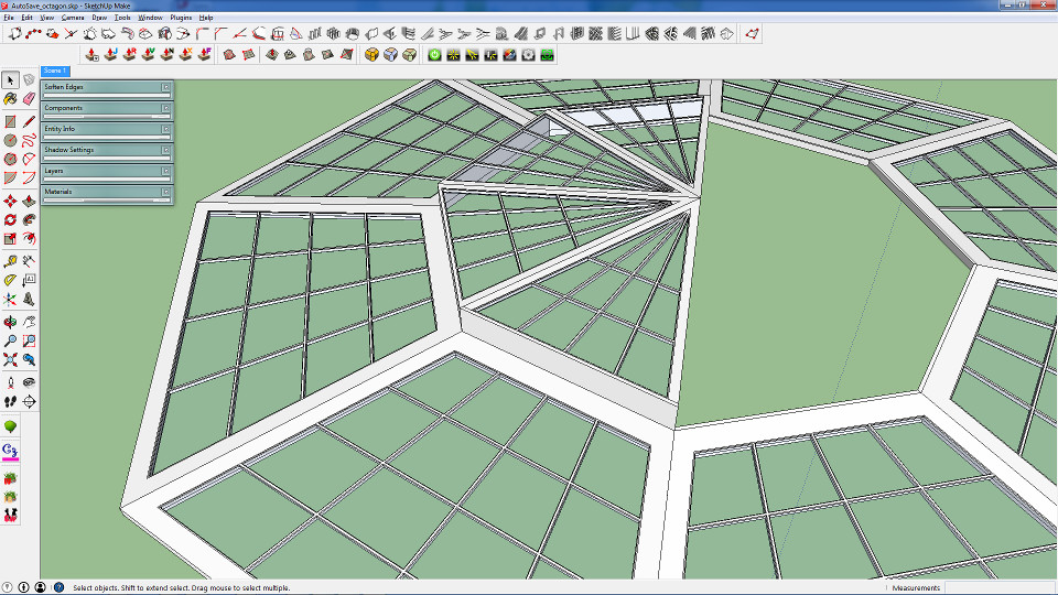
The line from the end of the peak to the side apex of the triangle is not square (in plan) to the center line of the building. It IS at one end of the building. But not where the skylight is. The skylight is also not square. SO it fits right where it is and the mirror fits, but it won't fit at the other end of the building.
Yes the mirror copy fits at the end where the skylight is. I'll send a file with the skylights placed and you can see where they fit and don't fit. I drew two lines as well that intend to show that the angle of one side of the skylight is not square.
-
IMO where the lights meet at the peak will be a problem for you. Have you considered a different approach say more like a rectangular grid??
-
Sorry for not getting back, I redrew the triangle, It was much better once I made sure that everything was lined up correctly. Unfortunately, I can't just make a squared roof bc it's easier. This design calls for a triangular point. I often have issues getting things to fit right, bc I'm not very familiar with actual construction, but I don't know any better ways to do things. Often the window maker on 1001 tools won't even make my window, maybe bc I'm causing an intersect?
-
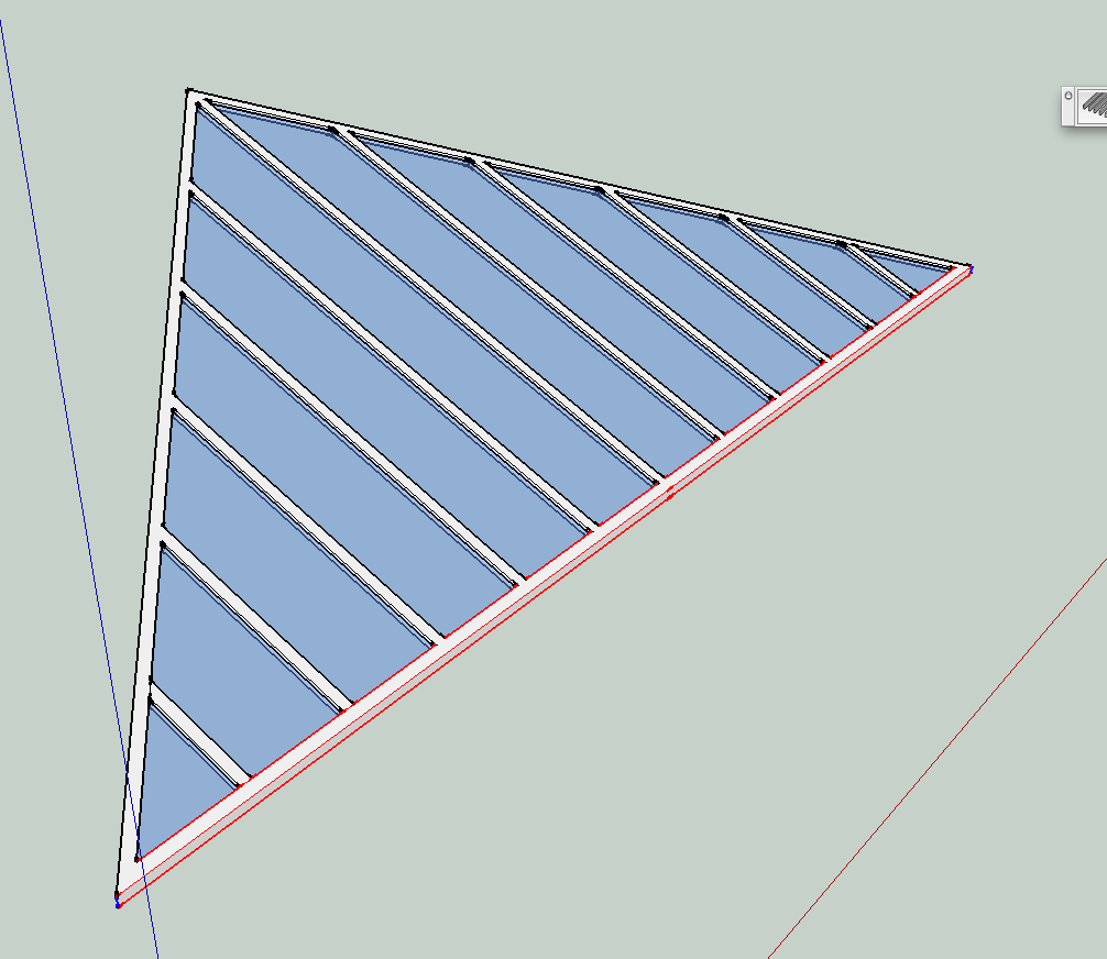
I think Mac1 means making the mullions as in the attached picture, plus some cross mullions as needed for larger spans (which I was too lazy to add in the example).
-
@sauronbloo said:
Sorry for not getting back, I redrew the triangle, It was much better once I made sure that everything was lined up correctly. Unfortunately, I can't just make a squared roof bc it's easier. This design calls for a triangular point. I often have issues getting things to fit right, bc I'm not very familiar with actual construction, but I don't know any better ways to do things. Often the window maker on 1001 tools won't even make my window, maybe bc I'm causing an intersect?
Il try one more time. IMHO you have your self stoved piped with one approach and not letting your self think out side the box. If you are stuck with the triangular approach you have shown then so be it but my original comment still applies about the interface at the peak. There are cost, construction, build feasibility and schedule issue that you should be considering and IMHO you have not, Have you even considered a "spider" approach at the peak so to avoid the congestion of that part. Unless the actual building is racked some way other than just model errors the rendering issue should not be of concern ( can be handled be monochrome during design and the only rendering during show and tell, use of scenes, layers) and of course you have already accepted impact of schedule and cost have been considered since design change is not allowed.
BTW it takes 6 degrees of freedom to define the location of a rigid body in free space ( x, y, z, pitch, roll, yaw) etc. and SU allows you to do that and not with standing model errors fitting should be doable. Also BTW just translation and rotation gets different results depending on the sequence -
GS sample1_8A..skpGS sample1_8A..skpAttached is a approach that does not use rotate nor scale but just offset tool and the push pull.
Several additional comments; One snippet of geo 852' off set from main model deleted; architectural units display precision is not adequate for accurate modeling IMHO so changed to decimal;
Su has the native capability of replacing one component with another and the replacement is added to model in accordance with how the new component and model axis are set.Both of those can be independently set plus the gluing plane can be set. This can allow the use of one component definition for all the lite's if model conditions are correct. (This is based on the fact component definition is invariant under scaling, rotation, moving but for the reason above this condition could not be meet.(The roof base triangles are not equilateral)
The attached portion of the model was simply done using the same Lite layout as the OP model and then the window frames will be created by a combination of off-setting to the required OP frame dimensions and the push pull to the required depth / height.
Double glazed lite's are required but only one side was done. IMHO a spider at top is still required to make the design reasonable as noted above. -
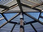
I didn't picture that at all when you said "rectangular grid".
@mac1 said:
Unless the actual building is racked some way other than just model errors the rendering issue should not be of concern ( can be handled be monochrome during design and the only rendering during show and tell, use of scenes, layers) and of course you have already accepted impact of schedule and cost have been considered since design change is not allowed.
BTW it takes 6 degrees of freedom to define the location of a rigid body in free space ( x, y, z, pitch, roll, yaw) etc. and SU allows you to do that and not with standing model errors fitting should be doable. Also BTW just translation and rotation gets different results depending on the sequenceI have to read your posts about 5-6x before they start to sound like English to me. Are you saying; 'the issues shouldn't be a big deal if I'm just rendering, not constructing in real life', and stating how much space I would need btw parts to actually build? Is translation the trick with going into scale, then typing "-1"? what do you mean by the diff results?
@mac1 said:
Attached is a approach that does not use rotate nor scale but just offset tool and the push pull.
Several additional comments; One snippet of geo 852' off set from main model deleted; architectural units display precision is not adequate for accurate modeling IMHO so changed to decimal;
Su has the native capability of replacing one component with another and the replacement is added to model in accordance with how the new component and model axis are set.Both of those can be independently set plus the gluing plane can be set. This can allow the use of one component definition for all the lite's if model conditions are correct. (This is based on the fact component definition is invariant under scaling, rotation, moving but for the reason above this condition could not be meet.(The roof base triangles are not equilateral)
The attached portion of the model was simply done using the same Lite layout as the OP model and then the window frames will be created by a combination of off-setting to the required OP frame dimensions and the push pull to the required depth / height.
Double glazed lite's are required but only one side was done. IMHO a spider at top is still required to make the design reasonable as noted above.While I appreciate the time and effort you put in to answering my q, I'm lost as to what you mean in the paragraph that mentions "geo 852'"(dunno what that is). I'm also confused as to what importing components has to do with the issue at hand. I think it would be easier to just redo the roof as I did, than to find/make new components to replace window panes. The main issue was not even the windows at all, the parts wouldn't fit bc the triangle was drawn wrong. Once I drew a good triangle, everything fit together. I know that windows can be made many diff ways, including push/pull, I made all the windows in my first model by dissecting a face with a plane and drawing every line by hand.
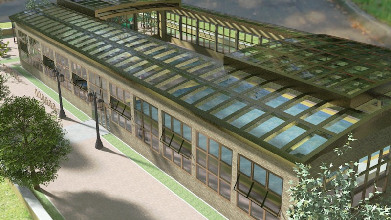
Now I'm smart enough to use a plugin, but that plugin was not working for the one window at the top. I was wondering if there was some reason that window wouldn't spawn, or what? even in the model you posted (2 copies of the same, right?), when I delete the lines separating the tip of that triangle above the row of holes you've cut, the tool will not make that face a window. Why not? Those were my 2 questions; Why no window, and why wont it rotate to match the mirror copy.
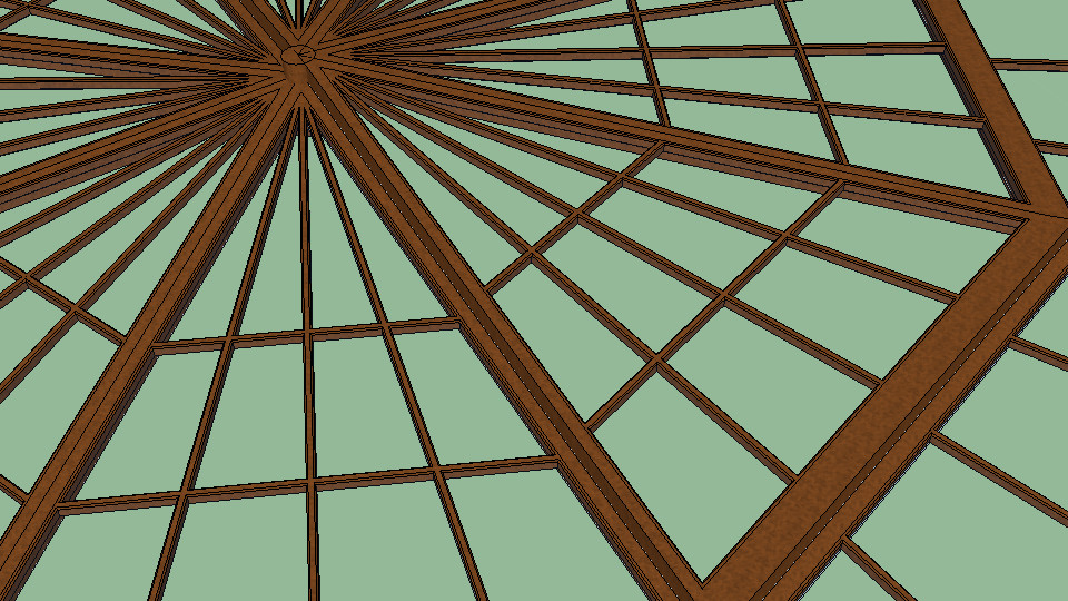
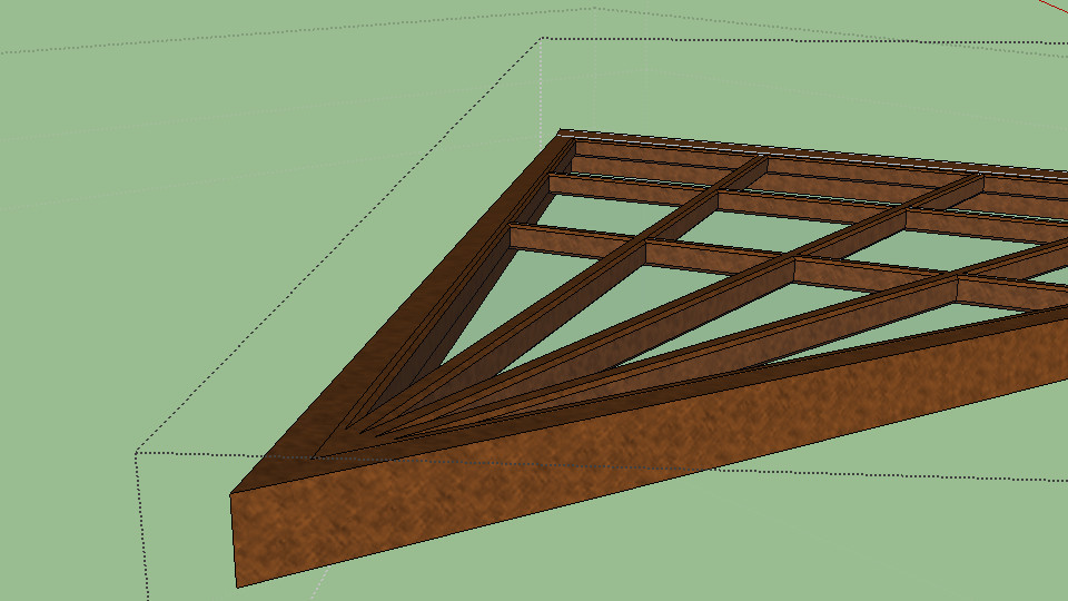
I now have that roof complete, the hard part was getting the 2 halves to meet in such a way that it would be possible for one side of windows to slide over the other, and I've represented that well enough to render(this isn't meant to be a construction plan). I'm still having trouble with the window frame tool. It refuses to work in certain areas, especially triangles. I've encountered a new issue, also. I've imported a few components, now my axes are all different. I cant draw rectangles on things bc the red/green don't line up with that component, so I must use lines. That or I wanna rotate something to match a wall, but it's not the same angle degree as the wall. For example: my wall is at 90deg. anything native to that group can be rotated to 90deg and fit nicely, but I gotta rotate this to 12.7deg or something stupid and hard to find. every component has a diff angle, like wth?? Is there a way to get them all on the same page, cuz it's a pain for me to rotate them just right, too easy to be off a bit.
As far as my progress, I wanted to stay with the look I had bc it went with the lower level of the roof, but yes, I did try a few styles when the first didn't work, you can see the new style has no equilateral triangle up top like before cuz the plugin wouldn't do it n I'd rather change styles than do all that by hand - I'm not "stovepiped" into any one idea.
-
Sorry I did not make my self very clear;
1)The dimension is 852 ft not 852 inches. It was just some extraneous geometry in the model that far off axis that would affect when you do a zoom extents;
2) The two windows in my last model are not the same. I will very seldom do a complete model for folks because I want them to learn by doing. The only reason for those two was to show how easy it is to make windows to you initial requirements;
3) Mirroring will not work because as the name implies the windows must have a plane of symmetry to mirror and the layout does not;
4) Using the architectural units is not very good model practice IMHO when working this type of problem. It does not give you enough display resolution to see when small errors are present. That is the reason I recommended decimal, with at least 3 places;
5) The picture of the spider is not what I had in mind. At the very top where all "parts" come together I think there some type of metical part to tie all parts together. Some what like you see on a geodesic dome, spider maybe not the correct word?
6) The approach I outlined to you makes drawing the windows very easy. You should try it.
All you have to do is two offsets of 1/2" each and then push pull [b]up 1" and 1 1/2" to make 1/2 frame and then repeat for other side, then add glass and you are done! [/b]The only down side is they will all be unique and number of detail drawings will have to made for a builder. Of course the drawing is just the first step. Static and dynamic analysis needs to be done. Where I worked we usually require a margin of safety of 2.5 at start and then reduce that down to 1.25 to 1.5 usually for final engineering release.
7)The rect. grid is as shown below by pabcot except I was thinking horizontal vs vertical and think that would allow you to work in the triangle at top.
8)[b] My discussion about replacing components was related as follows:
If I make a component of say the bottom left triangle< note I did not say frame> and the repeat that for the bottom right triangle> I can then very easily replace the right one with the left at the correct orientation and scale by setting the correct axis reference on the component and the model. There will be no manual rotation required, Su does that automatically as well as the scaling. The model issue did not let me do that.:shock:
9) Diff results=> I was trying to relate the sequence of axis translation and rotation can give different results depending on the sequence done and you should not let rendering be a driver in your design decisions, model using monochrome, do not use large photo image textures and keep ploy count down if possible (ie no circles with 100 vertices etc). SU moel can many times be made several different ways so when you have problems look for different approach or ask for early help so you don't get beyond point of no return , but that happens to some of us
[/b]Note that some of comments are based on my lack of knowledge. I don't know if you are doing a real design or just a concept drawing.
Advertisement


