Hi to everyone out there, and a question too
-
Hi, just signed up as there looks to be a lot of people doing a lot of good stuff - and solving a lot of problems that pop up. I am a basic user who is just stumbling though, watch youtude and has ideas beyond the means to do.
I am currently trying to draw up and trumpet for an intake manifold for a car engine. The base object is an 80mm dia "washer" with a 40mm hole in the middle. Next to it is the "trumpet" part done a simple crossection and then used a circle and the follow me tool to create it. Both parts have been made into objects and have volumes. I then place them together so the base of the trumpet and the washer align on the vertical axis and both objects overlap.
The problem is that when I use Outer Shell to get only the external shape SU creates it, but I can not get a volume from the (now singular) object. Would it be something to do with the the number of straight lines used to define the edge of a circle, or their position where they overlap? At present I dont have any answers as this does no seem to be something they noted in the guides for using solids. It did work well with 2 blocks, but anything I seem to do with cylinder or circles seem to give trouble.
Thank you for reading this far, and hopefully there are some ideas out there on how to get round this. Before I get too far ahead of myself I will read up on posting files and attempt a few as I fear I will have more questions than answers for a while.
Thank you for your time.
Clive
-
Share your file so we can mess it up.
-
Thanks for the reply Gilles. Hopefully it is attached now and someone can tell me where I messed up. It seems to be squares no problems, circles no end to problems.
-
Individually the two parts report as solid so it is just a matter combining them. You need get ref point on each to do that. Normally I would use the center point but the two 24 seg base dias do not have the vertices aligned so you will have to rotate one to align them. To combine they must be in the same context. To do that select one and cut, select the other so its is in the edit mode, select edit , paste in place.
There are two plugins ThomThom's solid inspector and TIG's solid solver that can help to make the item solid.
I question if you need to make the item a shell unless you plan on 3d printing and want to savee $ on thickness. If so I would recommend you use the stl exporter plugin and once you get that use Shapeways free tool ( very good tool) to correct holes and they will even report thickness so you have some idea on cost.
See http://www.shapeways.com/tutorials/how_to_use_meshlab_and_netfabb. SU now has a stl exporter so Meshlab step is not necessary.
Have to run to USP , will get back to you shortly. -
Welcome to the forum Clive...
-
-
 Some problem I have not been able to find.
 -
There's a couple of things with your model, probably already mentioned but I'll point one or two out anyway.
The circles you have used for the two parts are not aligned the same way and are a slightly different size. Make a note when drawing a circle that you pull it along an axis, this makes it easier to meet things together.You'll notice when using the circle tool that the radius line changes colour when on an axis. If it's black it will be hard to align to another piece, keep them green red or blue.The easiest way to make a round form like this is to draw the full profile including the flange and use follow me on a circle to create the shape. It will then be a solid object.
[screenr:2utko7il]J2UN[/screenr:2utko7il] -
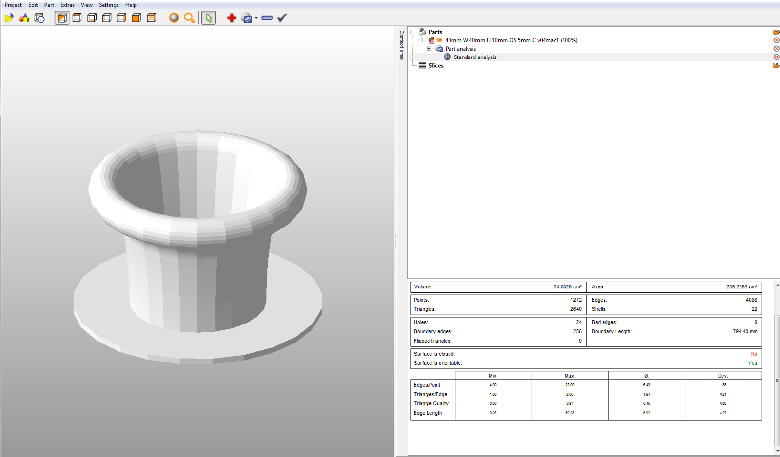
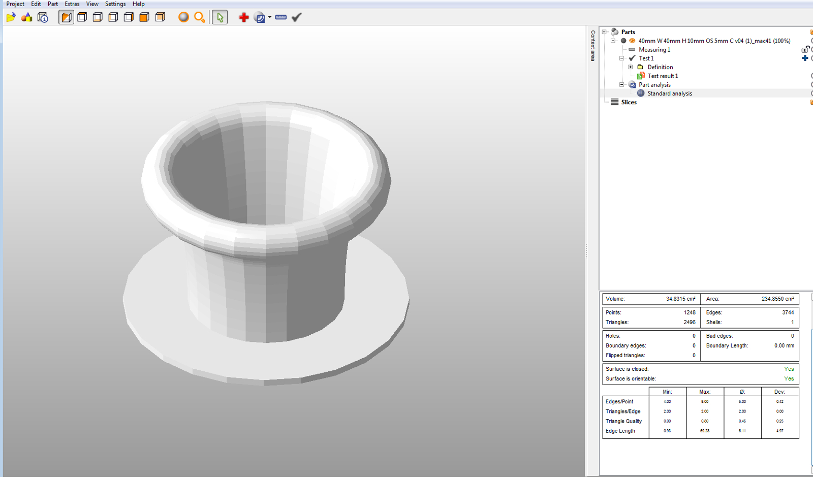 40mm W 40mm H 10mm OS 5mm C v04 (1)_mac4.skpBetter result vs. my post issue above
 -
Hi Clive, hi folks.
You can simplify your life if you use a single profile as shown in attached SU file.
-
Hi Jean,
Thanks for your information as I've been reading Sketchup for dummies, and while it is good generally it does not always point out the little things that need to be set up correctly. At present I am playing with a profile and trying to make sure construction lines etc are coloured to ensure they are on axis as noted by Box and in most part I have succeeded as when I use the Follow Me tool I do get a result.
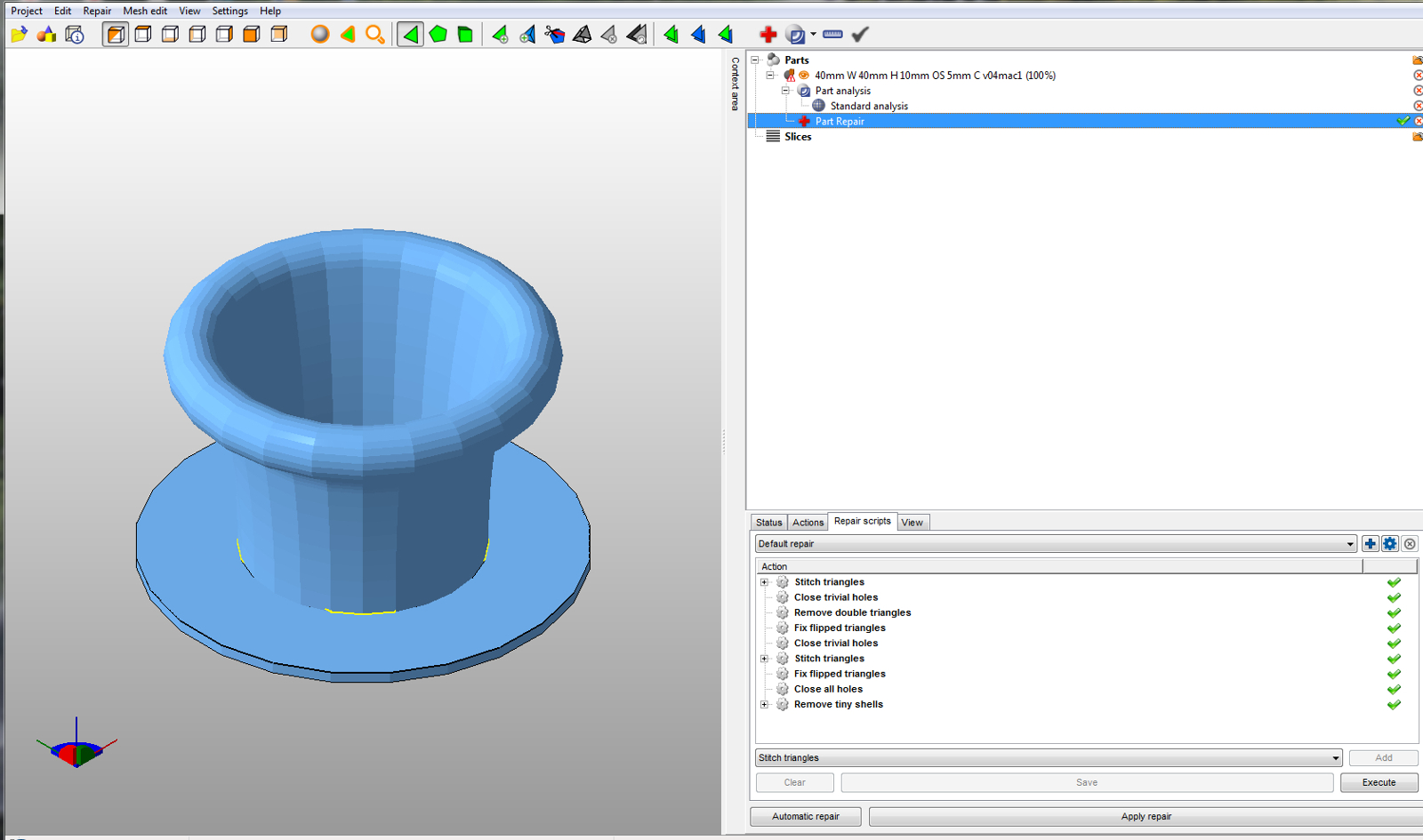
One problem that I'm finding with the profile seems to be how arc's are joined together (or more importantly how I am doing it. At the moment I create the top circle and then use ARC to click on the bottom inside curve and then the inside of the circle at the top, offset the arc to get thickness, add another arc on the outside under the circle, create the base, and then delete all the internal lines so that it shows up as a light blue face (I have had some white but they don't work). From there I use the follow me tool to complete the object - but, it seems like there is still a problem with the two inner arc's as a section does not appear in the object. It looks like it is from where the arc's join to the top of the tape measure line (see attached). Is it because they are not on the plane? The note in the box on screen when joining says "End Point" so is it how the join is made that is causing problems with that section of the circle? I also got the same problem when trying to put an arc in at the outside of the base and trumpet and that area has been left out when using Follow Me.
Straight lines do not seem to be a problem. When using freehand, reverse arc's, circles and offsets I can get complex shape to run, but when I try and calculate or get it mathematically right I hit problems. I know I am doing something wrong and its not the program as a 60mm one came out fine so therefore I want to find it, fix my method and get on to other commands and items.
Thanks for your time again.
-
The size of your object is most likely your problem. When you say a 60mm one works but this doesn't it's dead giveaway.
Sketchup has problems forming tiny or huge faces, tiny being roughly less than a millimeter. These faces can exist but are difficult to make.
When working down at small scale it helps to scale everything up by a factor of 10 or 100. Then scale it all down to size when done. Working in metric makes it very easy as everything works in 10s anyway.A couple of things about scaling or resizing.
Using the scale tool, preselect what you want to scale, activate scale, click one corner handle and drag a bit then type 10 and hit enter. To reverse this do the same and type 0.1 and hit enter. You can also scale a copy of a component up, edit and delete it and the original will have been edited.
Using the tape measure tool,with the tool active hit ctrl to remove the tiny + from the cursor, measure a known length then type the length you want it to be, ie 10 times whatever it is, and hit enter and it will ask if you want to resize the model, say yes and everything will scale up to be that size, to reverse do the same but put in the correct size.
You can also do this within a group or component so it only resizes locally. -
Thanks for that Box, I will give it a go and see if that cures the problem. I had been thinking that scale was immaterial as you can only see so much on screen and if you increase the amount of segments (in the case of circles) you get better definition and selection of points to click or accept - more reading required.
-
circleinasquare
I have been watching your post and have some comments / suggestions hopefully to help vs confuse:
More segments are not better. As that number increases the size of model MB wise gets larger, you run into problems of end point inference ( even to point of snapping to undesired point, color comes in handy here , some printers limit the number of triangles in the model ( ~ 1,000,00), and other issues like Box noted above plus many more like your graphics card performance. While you get up to speed keep segment count down to default;The issue of axis color is some what misleading. A color axis does not mean it is " on axis" per se but is parallel to that axis and so one can draw a infinite number of them. It is a another tool in the Su tool box to help along with the other inference tools. Just draw your profile on a plane and make sure it forms a face. It may even help to use small ref rectangle to start, the arc tool can do its thing some times and that will give you a on face ( plane ) inference point;
There are no tangents in SU in the classical math sense we were taught in school ,but that face profile must be perpendicular to the edge you are extruding around to start ( so if you attempt to start at a section of the segment line you have to make sure it is perpendicular to it. The first step in that extrusion process is a projection of the face along the first vector and will get changed in size if it is not or may not even work.
Instead of drawing the profile perfect to start( like you are doing with large seg count=> inference problem) start with a straight line approximation then lay in you arcs, circles etc.
Once you have a good SU model run it through the link I gave you above and it will give other info on printing acceptability( You can make a SU solid model that Printer's will not accept). That's one of many and is free.
Just some thoughts
Hello! It looks like you're interested in this conversation, but you don't have an account yet.
Getting fed up of having to scroll through the same posts each visit? When you register for an account, you'll always come back to exactly where you were before, and choose to be notified of new replies (either via email, or push notification). You'll also be able to save bookmarks and upvote posts to show your appreciation to other community members.
With your input, this post could be even better 💗
Register Login


Advertisement