Disappearing geometry?
-
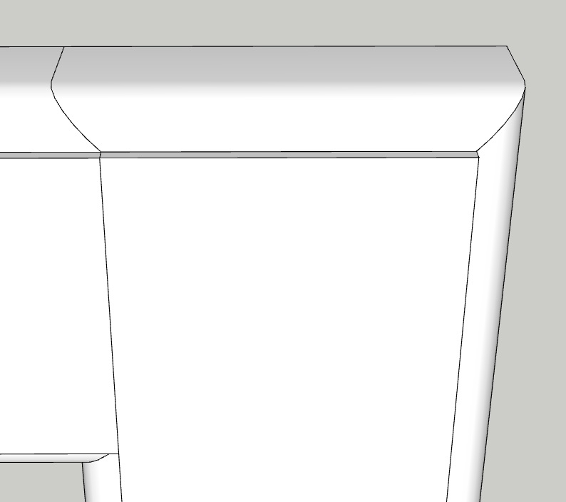
I'm currently designing a cabinet door, the rails and styles of which are symmetrical in cross-section, i.e. they have identical edge profile (outer edge) and framing bead (inner edge). i started by drawing a rectangle. then i placed the 2-dimensional cross-section of the rail/style on the edge of the rectangle and used the "follow me" tool to create the door frame (rails & styles) around the border of the rectangle. then i drew in some lines on the frame to indicate seams between individual frame members (2 rails, 2 styles, and 4 corners):
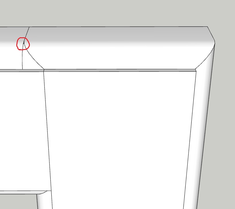
then i added another curved line (to one of the curved surfaces on the frame) that intersects with another curved line on that same curved surface, but as soon as i move that second curved line segment into place, a small piece of curved surface (part of the door frame) disappears near the point of intersection:
here it is up close...you can clearly see that a small part of the curved surface is now missing, and you can now see "inside" the door frame:
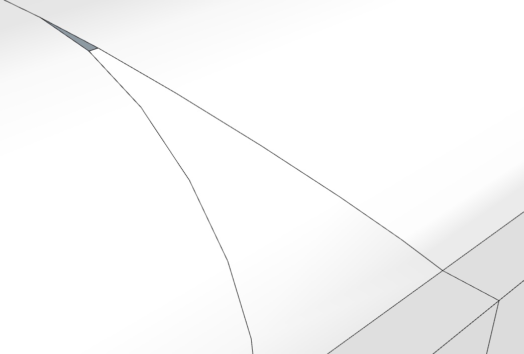
my question is why is it doing this? and if there's no way to keep that small piece of curved surface from disappearing on me, how do i fill that exact shape in with a curved surface of matching radius?
btw, i know this has very little to do with dynamic components, but i thought i would post in here b/c the door in question will actually be a dynamic component whose width, height, and thickness can change. that way if i have any DC questions, the thread is already here...mods please feel free to tow the thread to the appropriate section if this is not it.
TIA,
Eric -
You're creating a triangle that is so tiny SketchUp won't fill the face. You can prevent that from happening by scaling the model up by, say, 100x, before you draw the line that creates the triangle. If I were doing that, I would make a component of the thing before scaling up. Then I would make a copy, scale the copy up and edit it. When finished making the changes, I would close the giant copy and delete it leaving the original in place.
-
Regarding posting your question in the dynamic components forum, Many people don't bother to read questions in here because it's fairly specialist. Your question has had only 16 views so far, it would have had many many more in a less specific forum.
Dave has answered your question, but in future think about where best to post your question to get the most suitable audience. -
thanks for the quick responses guys...i could have sworn i'm set up to receive email notifications when someone responds to my threads, but i never got any email notifications...obviously i'm still figuring out this message board thing.
back on topic, i haven't tried the "copy and scale" method yet, but i did stumble across 2 other solutions today:
-
if i zoom in to make the small triangle of "missing surface" much more visible and then draw any random line across it (turning it into a trapezoid and an even smaller triangle), surfaces appear on both sides of the new line segment, filling in the original triangle. when i can delete the line segment, the newly created surface remains in place and leaves no void!
-
if i make a group out of all the edges, flat surfaces, and curved surfaces that i'm working with (or alternatively just highlight them all at once without making them an actual group), i can then use the "soften/smooth edges" tool on them. if i then make the "angle between normals" small enough (i don't know if it literally has to be zero or just a relatively small value), i can then place a curved line on the curved surface without causing any surfaces to disappear. i can then raise the "angle between normals" back up to any desired value and the curved surface remains in tact and unchanged.
-
-
It would be hard to tell without seeing it but my guess is you are only masking the issue. If you select the component, does Entity Info tell you it is "solid" or not?
-
It's also a hell of a lot easier to scale up and not get the errors than it is to fix them.
-
i'll check that tomorrow morning when i get back into the office...i'm on my way out the door right now...
-
ok, after having checked the entity info, i see nothing about the object being "solid." all i see in the entity info are the layer, name, and volume data boxes, and the hidden, locked, cast shadows, and receive shadows check boxes. come to think of it, of all the groups and components i've worked with thus far, i've never seen an entry in the entity info that says anything about the object being "solid" or not.
that said, i do believe what i've done has solved the problem, and isn't just masking the issue. i'll go through it in a bit more detail here, this time with a different, but sufficiently small triangle. this door, like the previous one, will be dynamic (adjustable in width and height by user input). as such, its frame members must be treated as individual components so that they don't distort when stretching the overall width and/or height of the door. there will be 2 rails (horizontal frame members, 2 styles, (vertical frame members), and 4 corners.
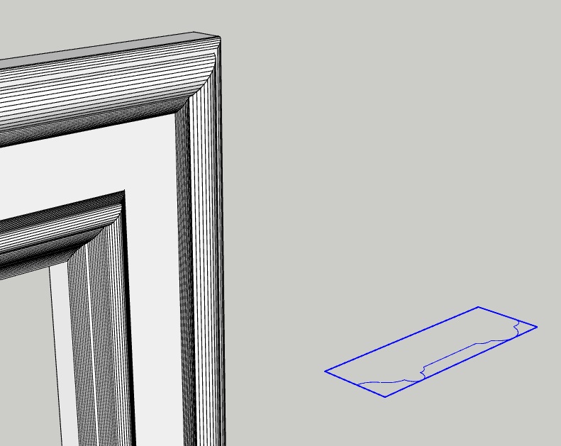
below you can see the top right corner of the door frame along with a group of both straight and curved line segments that comprise the cross-section of the frame...you'll see shortly that this group (and other groups) of line segments are needed to separate the frame into its individual members:
here is frame cross-section moved into place:
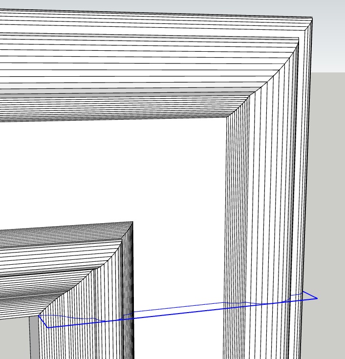
the instant i explode the group of line segments, a small bit of curved surface goes missing from the inside corner:
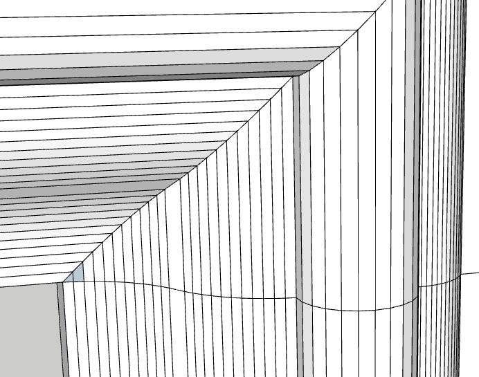
so anyways, when i get the other group of line segments into place and explode it, i get this:
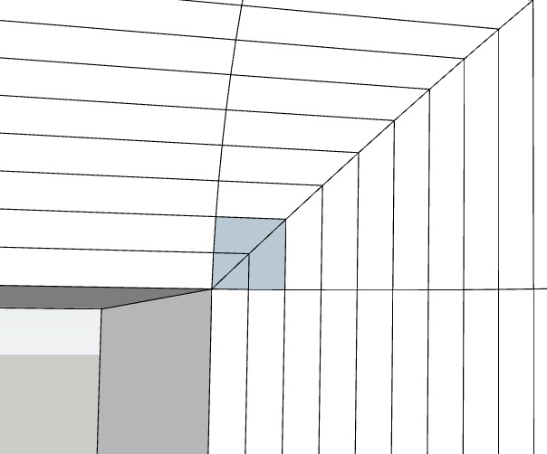
so now i have 2 little triangles and 2 little trapezoids of missing surface in the corner. when i delete the horizontal line that separates the missing triangle from the missing trapezoid and redraw it, i get this:
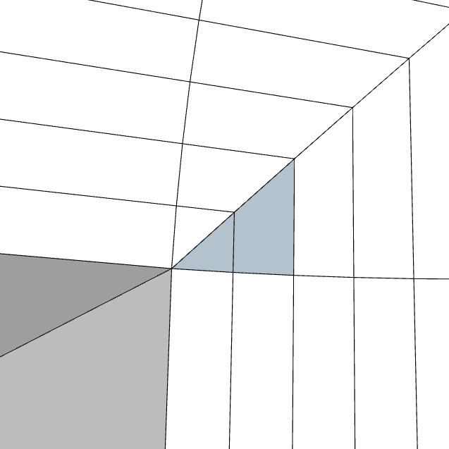
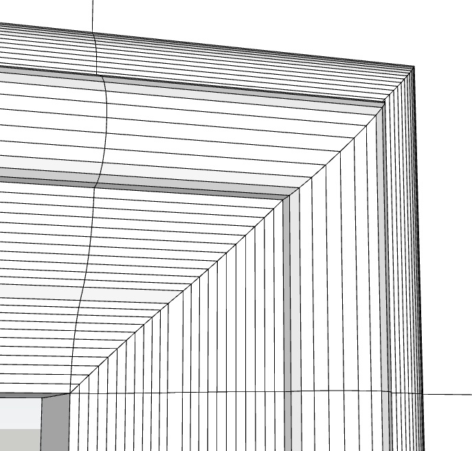
note that this doesn't work for me unless the "angle between normals" value in the "soften/smooth edges" tool is sufficiently small enough to render the curved door frame surfaces as groups of polygons...otherwise there are no lines or points (that comprise the edges of the polygons) for me to snap to with a line segment. so i went ahead and just set to "angle between normals" to 0, allowing the entire door frame to be rendered in as many polygons as possible. after doing this and redrawing the horizontal line segment as shown in the above picture, i then did the same with the vertical line separating the other two missing surfaces, and i ended up with this - a perfectly filled in corner:
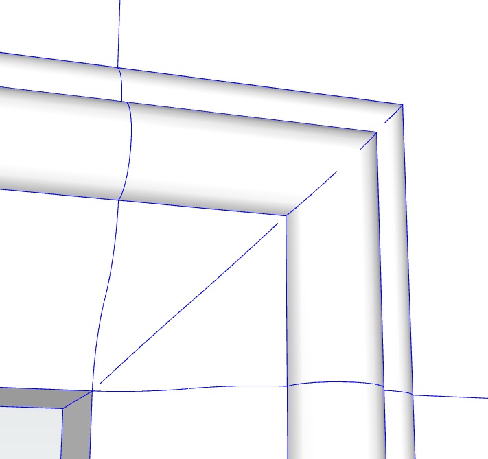
from here on out, it was as simple as selecting (or grouping) the entire door frame and using the "soften/smooth edges" tool to set the angle between normals sufficiently high enough to render all the polygons as curved surfaces again:
now correct me if i'm wrong, but this method seems to achieve the same thing as making the door frame a component, making a copy of the component, scaling up the component, fixing the missing geometry on the scaled up copy, and then deleting the copy but keeping the original. please let me know what you think.Eric
-
There is a phrase that springs to mind but I can't quite get the words in order, it's on the tip of my tongue and I'm sure it involves grand parents, eggs and some sort of content extraction..
You have a rather complex and creative work around that isn't needed if you create the geometry at a larger scale. If you have never seen a solid component, you need to look harder at your construction methods. Why is creating a component difficult, why isn't it one already? If you are having to soften your work to get the result you want then there are things wrong too. All those lines suggest you don't use welded curves, which makes for difficult geometry, things like missing triangles for example.
And why are you putting that profile in there anyway, personally I get more questions from your images and description than I do answers.
-
@cl said:
You have a rather complex and creative work around that isn't needed if you create the geometry at a larger scale.
i see now...i didn't quite understand why that is any different than my solution when Dave R first mentioned it, but something about the way you rephrased it made it click. i understand now how that would save me the time and effort of having to fix "geometry gone missing" at smaller scales.
@cl said:
If you have never seen a solid component, you need to look harder at your construction methods.
ok, i just did some research and realized that the entity info of a solid object doesn't literally say that its a solid, but rather indicates as much by defining a volume for the object. at any rate, only the center panel of the door (which wasn't in any of the above pictures b/c i hadn't drawn it yet). the reason the 2 rails, 2 styles, and 4 corners are not solid is b/c they have open ends. when the ends of these members line up to form the door frame, none of those faces will be seen (b/c they'll be inside the door frame), so i figured why draw unnecessary geometry? why render geometry that isn't going to be seen? now, if having drawn the 8 objects that comprise the door frame as solids from the onset might have also prevented the missing geometry, then i can see why all components of the door frame should be solids. i'll have to try that out and see what happens...
@cl said:
Why is creating a component difficult, why isn't it one already?
its not. i do it regularly when i need to. and the object in the above pictures is not a component yet b/c my dynamic door would not work correctly at all if the entire door frame was a single component. the rails would stretch and scale along with any change in door height, and the styles would stretch and scale along with any change in door width, not to mention the corners, which would be affected by changes in both door width or height. these objects need to remain unchanged in width, height, or both as the width and/or height of the door itself is changing...hence the reason the entire door frame is broken up into 8 components.
@cl said:
And why are you putting that profile in there anyway, personally I get more questions from your images and description than I do answers.
it is necessary to place them at all the corners of the door frame in order to separate it into 8 pieces that can be selected and grouped (or made into components) independently...and b/c drawing by free-hand the profile of the cross section onto the frame isn't an option...the straight segments can be done by free-hand, but the curved segments cannot.
-
The Entity info says Solid if it is solid.
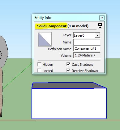
Your corner sections don't need to be right at the corner. If you create them further along the rail you won't have tiny triangles to worry about.
You don't need to insert a profile, use a flat plane and intersect the faces to cut through.
And as CL mentioned, it looks like you are using segmented curves to make your profile. You should weld your segments into one curve, or a least suitable sections. This gives you smooth geometry to start with and can help to reduce the tiny face effect. Even in your corner setup, if the surface of the rail is smooth to begin with adding a flat cutting plane right at the corner and intersecting is less likely to cause tiny triangles as you aren't putting several tiny segments near each other. -
doh...i didn't even notice the bold text at the top of the entity info box noting the component as solid! well either way, if its solid, its going to have a defined volume in the entity info box as well, and if it isn't solid, it won't have any volume info in the entity info box.
as for the cross section profile i've been using, i never thought of just intersecting a large plane at the same location to achieve the same affect, but i can see how that might be more desirable than inserting the exact profile i'm using. the reason i had the cross section profile in the first place was because i had to draw it and use the "follow me" tool around the border of a rectangle to get the extruded door frame in the first place...so i thought i would just use the profile again to separate the frame into its 8 constituent components. i'll try using a plane instead and see how that goes. also, i realize that the intersections don't have to be right at the corners, but it keeps the formulas for the size and position attributes of all 8 members simpler than if i were to move the intersections slightly away from the corners.
at any rate, i appreciate everyone's help...i'm leaving this morning for a wedding and won't be back until Sunday, which means i won't get to play with any of this until Monday probably...but i'll let you all know how these alternative methods work out for me early next week.
thanks again,
Eric -
ok, so i started playing around with some of your suggestions this morning, and here is what i've found so far:
-
i downloaded and installed the Weld plugin by Smustard, and it is very useful. the first thing i did with it was turn my cross-section profile into a single polyline. then i extruded it into a door frame using the "follow me" tool, and the curved surfaces created by the curved portions of the polyline turned out nice and smooth (as opposed to segmented into several flat faces that simulate a curved surface, as seen in some of my earlier pictures). of course there are some downsides too - for instance, once i place the polyline cross-section on the end of a frame member, it sort of breaks down into its individual line segments...i say "sort of" b/c at least the curved segments remain intact and don't break down into the segmented curves they used to be...so that's good from a "selecting multiple lines/surfaces" point of view.
-
i tried the alternative method of intersecting planes with the door frame near its corners to separate it into its 8 members. unfortunately this didn't work any differently than placing the cross-section profiles in the corners manually like i was doing previously, i.e. once i move the plane into place and use the "intersect faces" tool, the same small bit of curved surface goes missing again. honestly though, i didn't expect this to fix this problem. from what i can tell, the only difference between using a plane or the polyline cross-section to separate my frame into its 2 rail, 2 styles, and 4 corners, is that the plane method creates surfaces at the ends of each frame member, closing them off and making them true solids. i don't really know if there's an advantage to this b/c i don't know that the door's individual sub-components need to be true solids...and i've managed to successfully make quite a few door & drawer front models where only the center panel (and not the frame components) is a true solid. to illustrate my success, i'll upload some of those models here for you to download and play with...you'll see that the mitered doors are adjustable in width, height, and depth, and that the cope & stick doors are also adjustable in rail/style (frame) width:
- after having smoothed out segmented curves using the Weld tool, i still get missing surfaces in the corners...and so it appears that the original suggestion by Dave R that some polygonal surfaces are so small the SketchUp isn't drawing them is spot on. so i scaled the geometry up to 100X and separated the frame into its 8 members, at which point no surfaces went missing. i then scaled the geometry back down to the original size and the corners remained in tact. so drawing at a larger scale and then shrinking down the geometry seems to be the way to go in order to avoid SketchUp not drawing very small surfaces.
...so i guess the original topic of this thread has been addressed and solved, and i appreciate everyone's input thus far. that said, if anyone can elaborate on why solid components are more advantageous to work with than non-solid components, i would appreciate that as well.
thanks again,
Eric -
-
@94jza80 said:
...if anyone can elaborate on why solid components are more advantageous to work with than non-solid components, i would appreciate that as well.
while i was playing around with solid door frame components, i noticed that seams still show from certain viewing angles despite having made sure that i made those lines invisible. then i realized that it was a direct result of my having switched to solid components, or more specifically, having closed ends on my rails, styles, and corner pieces. when i first posted this thread, i was using open-ended (non-solid) frame components, and while i've since been given the impression that i might be better off creating and using solid components, my doors and drawer fronts definitely look better/more realistic when composed of open-ended (non-solid) components than they do when composed of close-ended (solid) components. here are some pictures illustrating this:
in this first picture you can see the "invisible" seams, even though they shouldn't be visible:
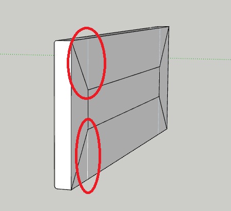
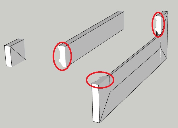
in this next picture, you can see that i've separated the top rail and the top right corner from the frame so that you can see the faces that cover the ends of these members, making them solid components:
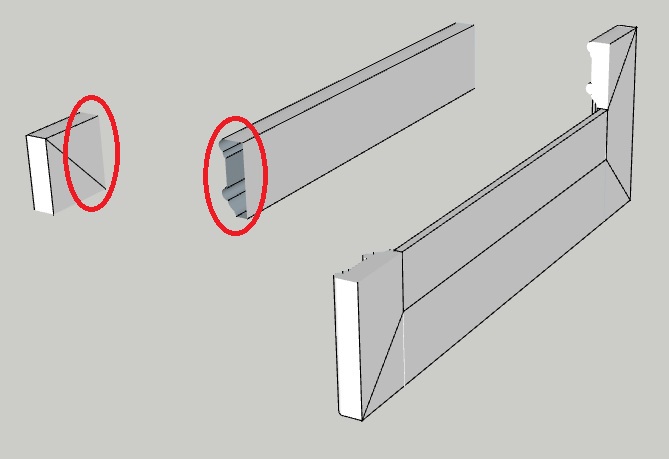
in this next shot, i've removed the end faces from the right end of the top rail and the left end of the top left corner piece (where the two pieces join):
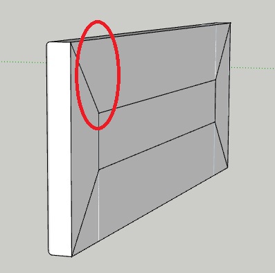
and finally, the top rail and top right corner have been moved back into place with the rest of the frame, and no seem can be seen whatsoever at the location where i removed those members' end faces (which made the solid components previously):
so i think its pretty obvious that leaving the end faces of the frame members in place is causing what would otherwise be hidden lines to show, even if it only happens at certain viewing angles...so there's one downside to using solid components...at least in the cabinetry industry where many components may actually be made of several sub-components.
-
I don't see anywhere in the thread anyone saying you have to be using solids. I believe Dave first asked if your method created a solid because if it was showing as a solid then the geometry had no holes in it. Retaining the end faces is only relevant when you Need a solid. Double faces create z-fighting so if two components come together generally at least one of the faces is removed to avoid it. Or as in your case, they aren't needed they create an optical problem, get rid of them.
How you model something depends on what you need the finished product for. There are very few hard and fast rules, although there is one that says SU always struggles to create small faces. -
@box said:
I don't see anywhere in the thread anyone saying you have to be using solids. I believe Dave first asked if your method created a solid because if it was showing as a solid then the geometry had no holes in it. Retaining the end faces is only relevant when you Need a solid. Double faces create z-fighting so if two components come together generally at least one of the faces is removed to avoid it. Or as in your case, they aren't needed they create an optical problem, get rid of them.
How you model something depends on what you need the finished product for. There are very few hard and fast rules, although there is one that says SU always struggles to create small faces.that is correct - nobody literally said i should be using solid components...its just that the way it was being talked about gave me that impression. now understand now that having a solid component guarantees that it has no holes...i don't know why i didn't make the connection before seeing as how one statement logically follows the other. anyways, thanks for clearing that up.
Eric
-
Edges can be hidden in solid components, just as well as other situations, if you want.
Advertisement


