sketchucation logo sketchucation
    • Login
    ℹ️ Licensed Extensions | FredoBatch, ElevationProfile, FredoSketch, LayOps, MatSim and Pic2Shape will require license from Sept 1st More Info

    Find plane at intersection of 2 vectors

    Scheduled Pinned Locked Moved Developers' Forum
    13 Posts 3 Posters 567 Views 3 Watching
    Loading More Posts
    • Oldest to Newest
    • Newest to Oldest
    • Most Votes
    Reply
    • Reply as topic
    Log in to reply
    This topic has been deleted. Only users with topic management privileges can see it.
    • G Offline
      Garry K
      last edited by

      I'm trying to get my head around finding a plane that is at the intersection of 2 vectors.

      Think of it as calculating the angles to cut a compound miter for moulding and the plane I'm after is the plane representing the cut surface of the miter.

      In sketchup I have 2 lines that intersect - I know where they intersect - but am not seeing how to derive the plane.


      The plane at the intersection of 2 vectors

      1 Reply Last reply Reply Quote 0
      • Dan RathbunD Offline
        Dan Rathbun
        last edited by

        if ipoint is the intersect point ...

        Would normalizing both vectors and using their sum method produce the normal vector for the miter_plane ?

        miter_plane = [ ipoint, vec1.normalize.+(vec2.normalize) ]

        ?

        I'm not here much anymore.

        1 Reply Last reply Reply Quote 0
        • G Offline
          Garry K
          last edited by

          I was thinking that adding the 2 normalized vectors together should result in a vector that has a plane which is perpendicular to the resulting vector.

          1. Maybe I'm going about this the wrong way. but I was hoping to use the plane to transform a moulding profile - but it would have to stretch in X and Y and rotate along the plane.

          2. Another strategy is to come up with this plane - transform the moulding to the first vector and use the points in sequence and intersect_line_plane.

          I'm just a bit slow at getting my head around all the necessary transforms.

          Have I left you totally confused?

          1 Reply Last reply Reply Quote 0
          • TIGT Online
            TIG Moderator
            last edited by

            #Assuming you have two 'lines' [i.e. line1=edge1.line etc] that you hope intersect ?
            ...
            pt=Geom.intersect_line_line(line1, line2) return nil unless pt vec1=line1[1] vec2=line2[1] ang=vec1.angle_between(vec2) nor=vec1.cross(vec2) tr=Geom::Transformation.rotation(pt, nor, ang/2) vec1.transform!(tr) miter_plane=[pt, vec1]
            If that's not it then rotate it by (ang/2)+90.degrees ?

            TIG

            1 Reply Last reply Reply Quote 0
            • G Offline
              Garry K
              last edited by

              Thanks Tig,

              That will work for strategy 2.
              This strategy may accumulate errors as I walk down the path. I will check it out over the weekend.

              1 Reply Last reply Reply Quote 0
              • G Offline
                Garry K
                last edited by

                I checked it out and it appears that the miter_plane is always vertical and not a compound miter. What I was looking for - like on a compound miter saw is to change the angle of the miter saw so as to cut a compound miter.

                What I am missing is how to rotate in 2 planes at the same time.


                Simple miter works


                compound miter does not work

                1 Reply Last reply Reply Quote 0
                • G Offline
                  Garry K
                  last edited by

                  What is really interesting is that Dan Rathbun's solution produces the same plane as does Tig's, except Dan's does it with 1 line of code.

                  miter_plane = [ ipoint, vec1.normalize + vec2.normalize ]

                  1 Reply Last reply Reply Quote 0
                  • TIGT Online
                    TIG Moderator
                    last edited by

                    Did you use the 'cross' to get the axis of rotation ?

                    TIG

                    1 Reply Last reply Reply Quote 0
                    • G Offline
                      Garry K
                      last edited by

                      I believe that I did

                      v = vec_1.clone

                      ang = vec_1.angle_between( vec_2 )
                      if ( ang != 0 )
                      nor = vec_1.cross( vec_2 )
                      tr = Geom::Transformation.rotation( pt1, nor, ang / 2.0 )
                      vec_1.transform!( tr )
                      miter_plane = [ pt1, vec_1 ]

                      p3 = []
                      for pt in p2
                          line = [ pt, vec_1 ]
                          p = Geom.intersect_line_plane( line, miter_plane )
                          p3 << p
                          ent1.add_cpoint( p )
                      end
                      

                      end

                      1 Reply Last reply Reply Quote 0
                      • G Offline
                        Garry K
                        last edited by

                        I found an error where I was setting z to 0 for the vectors - I changed that and I am getting closer.

                        At least I can get a compound plane with Dan's code. I have several errors doing it the other way and have to test for ang != 0 and now also test for transformation.rotation as it says it can't create a vector that has 0 length.

                        I'll keep chunging along !

                        1 Reply Last reply Reply Quote 0
                        • G Offline
                          Garry K
                          last edited by

                          Ok - the premis for my strategy 2) is flawed. The code works - but produces a twist in the profile as it changes elevation.

                          strategy 1) is still not figured out.

                          The way I have been handling this is first of all transform scaling in the x direction. Then rotating and placing. It produces a result that will work but only if there is a consistent pitch if working with an elevation change. This is the second picture.

                          The problem here is if we start changing the pitch to close to vertical then the shape is wrong.

                          It appears that there has to be a compromise Conceptually if I use strategy 2 and come from both sides the intersect_line_plane will produce points that do not meet. Perhaps taking the midpoint between each pair ( 1 pt from vector 1 and the other pt from vector 2 ) it may produce an acceptable compromise. Just speculating as it is a bit difficult to visualize.


                          Strategy 2 is twisted


                          Scale, then rotate and place

                          1 Reply Last reply Reply Quote 0
                          • TIGT Online
                            TIG Moderator
                            last edited by

                            If you think about the real world...
                            It's quite possible to have two profiled cross-sectioned extruded objects [like handrails] meeting on a center-line but being rotated in the long axis.
                            Thus, if you cut mitered ends they will meet with a common miter-face BUT the various vertices of the profile's face will never match up.
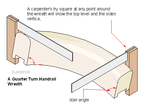
                            It's just a fact of geometry...

                            That's what joiners invented 'wreathing' to join two profiled handrail sections neatly at a major change in direction...

                            http://www.builderbill-diy-help.com/image-files/sloping-90-wreath.png

                            http://www.dressermouldings.com/store/media/catalog/product/cache/1/thumbnail/600x600/9df78eab33525d08d6e5fb8d27136e95/r/i/risingwreath.jpg

                            TIG

                            1 Reply Last reply Reply Quote 0
                            • G Offline
                              Garry K
                              last edited by

                              I know exactly what you mean - I've built a lot of curved staircases.

                              The challenge when it comes to modelling is to try an approximate the handrail profile and to manage ( or control ) the distortion. You feather the distortion over a distance so as to minimize it visually.

                              1 Reply Last reply Reply Quote 0
                              • 1 / 1
                              • First post
                                Last post
                              Buy SketchPlus
                              Buy SUbD
                              Buy WrapR
                              Buy eBook
                              Buy Modelur
                              Buy Vertex Tools
                              Buy SketchCuisine
                              Buy FormFonts

                              Advertisement