[Plugin]Hole on Solid tool v1.6.3 upadate Jan 09, 2012
-
Thanks for this plugin, I love it!
I did have some trouble with they sketchy physics plugin though, somehow they conflict, and it caused the plugin to combine the face and the solid into a group, with no hole created. After hunting for an hour or so, I finally realize it was the plugin I had added this morning causing it.
-
@zaaephod said:
Thanks for this plugin, I love it!
I did have some trouble with they sketchy physics plugin though, somehow they conflict, and it caused the plugin to combine the face and the solid into a group, with no hole created. After hunting for an hour or so, I finally realize it was the plugin I had added this morning causing it.
Hi,zaaephod.
Thanks for your enjoying.And the problem was already solved?
If not,Is the problem caused to hole on solid?Thanks.
-
Tak2Hata,
Thanks for the plugin. It was frustrating trying to use this - I watched your youtube video three times, and even allowing for the different (Japanese) Skethchup version, I couldn't get anything to happen...but finally figured it out while writing this!
You replied to another user who had my problem, above:
cjc0306 wrote:
Once I click on the Hole on solid button I cannot selet the items. The selection arrow is shown but nothing gets highlighted or selected upon clicking. SU version Im using is 8.1.16.Hi,cjc0306.
That flow of tool is like this.
Start this tool.
Click Group/Component.
Click face for hole.
I think you selected face first?My best clarifying rewrite:
- create object to be drilled and save as group or component
- create shapes to use as "drills" that will extrude holes in that solid
- float those "drills" above the face/s of the solid such that their shadows will extrude the holes in the desired locations
- turn on Tak2Hata's drill tool (look for floating menu to confirm it's on)
- note that instruction text (bottom of screen) will say "select first solid"
- select the object to be drilled (as group or component)
- the grouping to be drilled will highlight in blue
- note instruction text will now say "select face for hole"
- click on the group's face that is to be "drilled" - and note that there will be NO visible response to this - that is, there is no indication that you've succeeded in selecting a face; also, the arrow-cursor will seem "dead" at this point (it moves, but can't select anything other than a drill-shape)
- keep the faith, and click on any of the "drill" shapes you made previously
- a hole in that shape will be extruded through the object (I'd add an explosion sound there if I knew how...)
I've only done this once successfully, but I think this is about right. Please feel free to edit/use my clarifications to help instruct others.
--Dave
-
Hi,david.
Thanks for your reply.
I will write the annotation about the solid in sketchup must be Group/Component.
TAK2HATA
-
Tak2Hata,
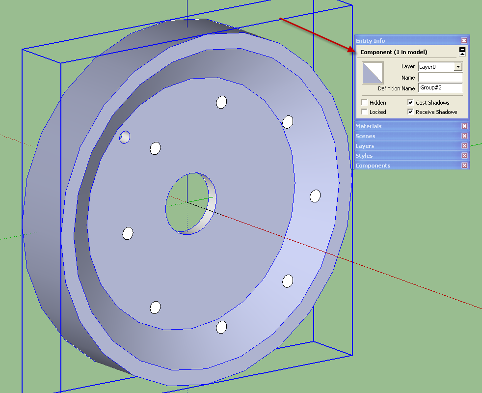
I've had only a little success in using your tool in my actual project. I'm trying to 'drill' eight holes, on a circular pattern, through a simple wheel shape.
I am guessing that the tool can't "drill" using my grouped "drill" shapes. In my case, this is the eight 1/2" discs that are floated above the surface of the wheel to be drilled (there was no response when I selected the grouped "drill" shapes.)
I ungrouped them, and only then was able to make one hole. And that would be OK - I could do it one at a time - but Sketchup crashed as soon as I tried to make the second hole. I managed to save it after one hole was drilled, but each time I restart and try again, it crashes.
I also of course noticed that after my first test use of your hole-in-solid tool, I no longer see the floating menu. I have been selecting your plugin from the menu, but the only indication it is on is the text in the bar at bottom of drawing.
Any suggestions?
Thanks - Dave
-
Hi,Dave.
Please uploade the model of that problem.Thanks.
-
@tak2hata said:
Hi,Dave.
Please uploade the model of that problem.Thanks.
Tak,
Thanks for the offer to help. File is uploaded.
I no longer see the "tear-off menu" for your plugin, though it responds as if it should still be working. It has always been the case that I never know if it's going to "punch" a hole until either it does so, or it crashes. Should it be capable of punching a group of holes through the selected solid face? And how does the user know when a face of that solid has been successfully selected?
Mahalo - Dave
this one crashes or does nothing when I try to make any more holes.
-
Your component is not solid.
Also there are lots of bad geometries.
Redraw from scratch is a one minute job then this works. -
Hi,Dav.
Gilles said opinion,I think so ,too.And I tested the boolean operation on sketchup.It could not be drilled because it is not solid.
I will consider this problem in future.But it will take longer time.
You said no longer seeing "tear-off menu".
Delete this plugin from your plugins folder.
Never mind for never use my plugins.
-
@tak2hata said:
Hi,Dav.
Gilles said opinion,I think so ,too...It could not be drilled because it is not solid...Not solid? Did you orbit the wheel, and notice it has two holes punched in it (one in center, the other being one of the eight 1/2" ones, both punched using your plugin? (What defines 'solid,' if that isn't solid?)
I don't know what Gilles means by "bad geometry," perhaps it needs to be punished. I drew this as a 'solid of revolution,' that is, by drawing the upper half of the wheel's cross-section, and extruding it along a circular path, using the follow-me tool. The default circle SU draws (and which I followed) is 24-sided, so this results in some 'jagginess.' That imprecision wouldn't matter in my view, because my "simple plan" was to pdf and email this drawing to some casting shops to get rough quotes: they would glance at the drawing, want to know the overall diameter and the thinnest section, estimate the weight, and they'd be done with it.
So I started from scratch yesterday and mostly repeated what I had done before, to refresh my memory of how I'd drawn the thing. Most of the same problems recurred. I could not successfully specify a 7" radius for the 'follow-me' circle, for example, but was able to mouse-click to meet the wheel's 14" diameter. I had to do a temporary construction of a couple of rectangles in order to convince SU to draw the center-hole on the red axis, which otherwise couldn't be selected at any view. But this time, the hole plugin worked, for whatever reason, one hole at a time, but the tool palette seems gone forever.
-

It isn't solid or SketchUp would show it as Solid Component. There are quite a number of internal faces which make it not a solid. If you look at the wheel in X-ray face style and with Hidden Geometry turned on you'll see all the "bad" geometry.
The simple definition of a solid component or group in SketchUp is that every edge borders exactly two faces, no more and no less.
You seem to be ignoring the assistance that I and several others have tried to provide in your related thread.

-
Dave R,
Please have a look at the attached redo. I've never used xray views so not sure if you mean that's part of how you assess "solid" vs "not solid" (solid = "no leaks?"). I'd never paid much attention to "entity info" heretofore, but that looks like it's the yes/no indicator of solidity or lack thereof?
Anyway, I went to my previous iteration and looked at it to compare with the newer one, and to guess at what I should be/am seeing when using Xray view settings. Recall that both versions were rotationally-extruded, with the first following the default 24-sided circle; I think that's the source of what's being called "bad geometry," but maybe that was gilles' verdict just because it's jaggy. OTOH, the attached version should be essentially the same, though differently-meshed, since it's extruded following a 100-sided circle vs. 24.
If it's a question of "leaks," I don't know where those would be. Both that version and the new were "solid enough" to punch with the plugin tool - though the first one got all crashy after the first hole was punched, the second version didn't.
-
This is good geometries you can compare your model with, note that all the holes were made at a time with Hole on solid.
This takes me less than 5 min.You may update your profile to newbie.
-
The geometry of your wheel this time is correct.
-
@unknownuser said:
I think that's the source of what's being called "bad geometry," but maybe that was gilles' verdict just because it's jaggy.
This is not about jaggy, in your first model there are lots of unneeded faces lines etc... preventing to create a solid,that was what I meant saying bad geometries.
-
Hi,pants.
You "no longer" use this "tear-off menu".
Wake up from bad dream.I will consider this problem in real.
Good bye.
-
@dave r said:
The geometry of your wheel this time is correct.
Thanks - though I still don't know why there'd be a difference between the two, other than the 24-side circle vs the 100-side later version I used. Meh...time to move on. Appreciate your input.
-
@tak2hata said:
Hi,pants.
You "no longer" use this "tear-off menu".
Wake up from bad dream.I will consider this problem in real.
Good bye.
I can't tell if you're revoking my seat, or fixing the plugin, but thanks for the plugin anyway, since it's doing what it should do in the later version of my simple drawing.
-
@gilles said:
...
This takes me less than 5 min.You may update your profile to newbie.
Oh, yeah, I'll get right on that change to "newbie" - anything to get more of your detailed, patient explanations.
-
@pants said:
@dave r said:
The geometry of your wheel this time is correct.
Thanks - though I still don't know why there'd be a difference between the two, other than the 24-side circle vs the 100-side later version I used. Meh...time to move on. Appreciate your input.
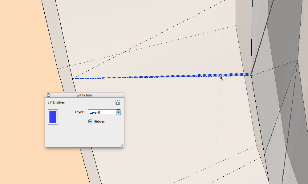
If you turn on hidden geometries and X-ray you will see the problem ( picture).
Your wheel = 1712 entities, the same wheel well drawn = 484 entities

Advertisement


