Need a little help to get started...
-
Hi everyone.
Well today is the day I decided I really need to learn to basics of DC's as I am helping a mate with his kitchen and he wants me to give him DXF files with cabinet parts (shapes of panels with drill marks on them)
So I thought......What an easy way to introduce myself to DC's......FAIL !!
As an example of what I set out to do....
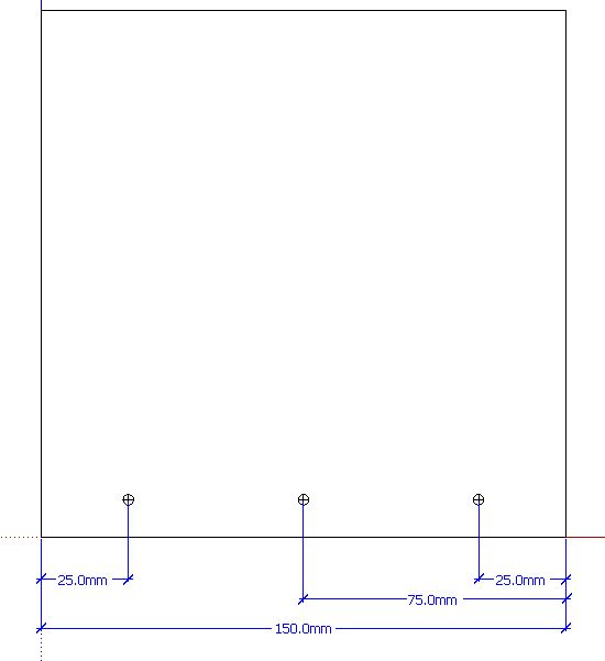
I created a small panel.
I then created a 3mm crosshair to place on the panel. I want these marks to remail 25mm in from each end and one in the centre. I also want them to be 8mm up from the bottom.
I set up two input boxes to set the size of the panel.
Before I tried to add a formula to parametrically position these marks, I found that when I resized the panel the marks were squashing or stretching.Now I don't think I could have chosen a more simple thing to start learning DC's but I am stumped already and not being one for thinking like a programmer I will probably remain stumped!
Can anyone help start me off with this as I have lots of drill mark options I need to explore but I just need to get through this first hurdle.
cheers...Wayne
-
Hi Wayne,
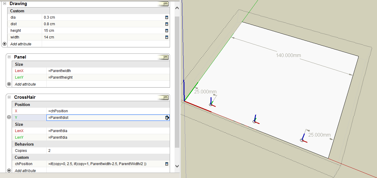
To keep the crosshairs from becoming distorted, you need to constrain their length and width. Do this by setting their LenX and LenY attributes to
=3mm. (Assume you are working on the Red-Green plane.)If you change the origin of the crosshairs to be at their centers, this will make the position formulas simpler. (Assume you wll use 3 unique crosshair components.)
With the origin at center, the middle crosshair can have a position of
panelWidth / 2The left crosshair would have a position of
=25mm, and the right a position ofpanelWidth - 25I've attached an example file - open it in SketchUp (rather than Import it in SketchUp.)
I've shown a different technique for the crosshairs in the file. Instead of using 3 unique crosshar components, I use the Copies attribute to create the 2 extra copies (so there a 3 total crosshair components.) Then use some nested IF statements to set the crosshair position based on their Copy number.
-
Thanks so much Jim. That gives me a simple insight and a kick start!
I don't think I'll get into the if statements just yet but I will work toward it for sure.
cheers...Wayne
Hello! It looks like you're interested in this conversation, but you don't have an account yet.
Getting fed up of having to scroll through the same posts each visit? When you register for an account, you'll always come back to exactly where you were before, and choose to be notified of new replies (either via email, or push notification). You'll also be able to save bookmarks and upvote posts to show your appreciation to other community members.
With your input, this post could be even better 💗
Register Login


Advertisement