Engraved sign maker, technique, or plugin
-
@dan rathbun said:
@dave r said:
The baseline would be at the bottom of letters that aren't round. i.e. r, h, k, f, etc.
Not true ...
[attachment=0:28fm8x47]<!-- ia0 -->baseline.png<!-- ia0 -->[/attachment:28fm8x47]
The baseline of the text is at the bottom of the f and r. The o and e drop below the baseline.


Certainly, if all of the text is to be the same size, you could enter it in as a single block although I can think of cases where even with the text being the same size you might want it to be in separate components for placement purposes. I wasn't changing any conditions. I was just trying to illustrate my original point that the center of the component's bounding box may not be the best reference point for placing 3D text.
-
Here we are confusing the text's baseline [the bottom of non-cursive characters - the line on the sheet of paper if you will], with the 3d-text component's 'base-line' which is its boundingbox's 'minimum' edge - so with 'TEX' it's the bottom of both characters, with 'COT' it will be the bottom of the C [or O], but with lowercase like 'Coy' it will be well down at the bottom of the 'y' !
As I just said you can relocate the components axes so they align wherever you like...An alternative to text that includes mixed fonts or heights, subtle alignments etc is to make a large PNG of the text 'set out' using a suitable app, give the background full transparency, then use it as an Image in a SKP and use my ImageTrimmer to make a 'cutout'; accepting simplification of the edges to avoid pixelated steppiness.
Then edit the component to remove unwanted materials and perhaps unhide the edges, and if needed explode/merge and PushPull the outlines into a 3d object... -
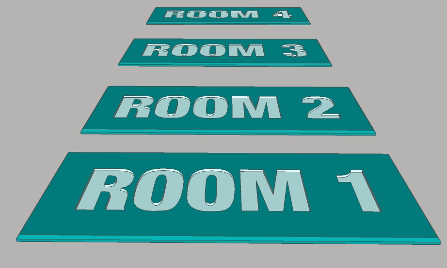
Here are my signs, interestingly enough I thought the real versions of signs like this were cheap...wrong. Selling as high as $36 each, as low as $8.95 each. I am in the wrong business. The margin (profit)on these must be quite large.

-
How big are they?
The place I work has their own sign shop which, at the rates you quote, is probably a very cost effective thing.
-
@dave r said:
I was just trying to illustrate my original point that the center of the component's bounding box may not be the best reference point for placing 3D text.
I totally agree with you on this point Dave !
@tspco said:
Dan, as far as I know you cannot use different letter heights in the text box.
For example TSPCo (my company) is in a two foot height. And Conceptual Design (a division)is in 1 foot high letters. So maybe an ability to use different height letters in the 3D text dialog, is all I want. That may be easier.Ok.. now I understand your needs ...
OK so add 3 more 3DText feature requests:
(e) font per line
(f) height per line
(g) line spacing per line -
Dave these signs are 3"x8", based on what is available on a couple of webpages that sell such things.
Dan, yup that pretty much nails it, if such a feature was implemented, even as an extension that can be turned "on" at the users discretion, like the sandbox tools.
-
@tspco said:
Dave these signs are 3"x8", based on what is available on a couple of webpages that sell such things.
Well since the invention of the FlowJet making signs like this should be much less expensive than the old router engraved signs.
The flowjet would cut out the top layer in a fraction of the time that a router could engrave them.
Then the cut out layer is glued (or fastened with hardware,) to a backing layer. -
After working on a plugin to satisfy this request, the three things that .add_3d_text needs most is
-
A text alignment that really means something as this video demonstrates.
[flash=640,480:1oeov0o2]http://www.youtube.com/v/UmZZfMXefiQ[/flash:1oeov0o2] -
A parameter to locate the origin of the text rather than always being created
at the model ORIGIN. -
A parameter to define the normal of the text rather than always [0,0,1].
-
-
Well to mimic the native tool...
you first create an empty group (so you have a reference,)
Then you add the 3dtext to that group's entities (not the model's)...
... then you transform that group, translation, rotation, etc.
or.. set the selection set to only the textgroup, and call the MoveTool with
Sketchup.send_action() -
The 3d text alignment argument only works on 'multi-line' strings (adding "\n" in the string will do this for you) then the lines are arranged left/right/center; otherwise a single line is just that.
If you add the 3d text inside a group or component-definition instance then it's straight forward to find its bounds.center, to convert that to to the bottom face use
cpt=group.bounds.center; cpt.z=group.bounds.min.z
OR .max.z for the 'top'.
Or any other point on the bounds [left/right/center etc]...
Once you have this you can get the translation vector to the required insertion point and transform! the group to suit. If you want the group's axes to be say central you can transform all of the group.entities en mass by the translation transformation so they are centered at the origin and then do the translation to the required insertion point...If you add the 3d text inside a group or component-definition instance then it's straightforward to transform-rotate it in 3d so that its 'normal' [blue/Z axis] faces any direction you desire...
So for the last two your custom 3d text tool spec can include all of the required options, plus an insertion point and a 'normal'.
The way I do this with 2dText or AreaTag is to make it a component instance and glue it to a face, so the normal is set from the face, the picked point sets the location...
-
Dan,TIG
Adding the 3d_text to a group is what I finally did and, as you suggest, I used the group.bounds.center and face.bounds.center to create the translation transformation. That worked great on horizontal faces. In order to get it to work on inclined or vertical faces, I had to convert the group to a component where I could use the face.bounds.center and the face.normal to define the transformation for adding the instance.
A funny thing about the multi-line text input. Adding the '\n' to the string worked in the web console but, when I entered the same text into the inputbox, it was made part of the text.
-
The \n must be inside "", because inside '' it is read literally.
-
@tig said:
The \n must be inside "", because inside '' it is read literally.
Well maybe it's me but I have used no quotes, single quotes, and double quotes along with .to_s and without when assigning the string to a variable and the results is always the same. Everything in the inputbox is treated as a single text string.
-
You MUST use
text.gsub!(/\\n/,"\n")to convert any '\n' in a string that has been passed from a dialog to include a true 'newline' in the string that you subsequently pass to 3d_text... perhaps this is the issue.
-
TIG, Thanks for the tip. That works! The gsub function remains a mystery to me.
-
@sdmitch said:
The gsub function remains a mystery to me.
The "sub" stands for 'substitute' and there is a
sub()method also (but it only makes one substitution.)Not sure what the "g" stands for.. 'global' perhaps ?? (it makes makes as many substitutions as it can.)
-
Back to the original question of how to engrave text: if you have the Pro version, the solid tools make combining the 3D Text component and the rest of the model easy.
For the rest of us, a few lines of Ruby make it easier to select all those faces and fill in the missing holes. See http://www.instructables.com/id/Engrave-3D-Text-With-Sketchup/
Advertisement


