Hidden geometry head scratcher
-
I've been playing with SU for a couple of years now, ever since Gary Katz over at JLC forums introduced it as a great design tool for carpenters. Love the program.
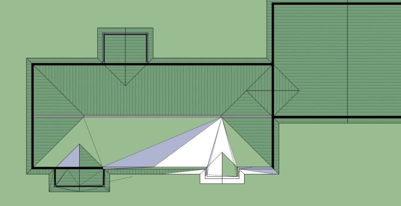
I've built several fully detailed models of various houses and commercial buildings my company owns or are developing, and it seems that I keep running into the same problems, and I'm not even sure how to describe it to properly search for answers. The current project I'm working on is a simple 3 bedroom house, and I'm currently working on a 2D roof plan. I've drawn the entire thing in parallel perspective, top view. This drawing is strictly 2D, and will not be extruded.
I lay out all of the lines, connect the dots for my hip and valley lines, and start filling in texture (using the stock metal roofing). When I started on the main roof planes, it only fills in a little bit in strange triangle patterns. Filling in one single 'face' entails clicking dozens of various triangles emanating from places where no lines exist. Turning on "hidden geometry" reveals a labyrinth of lines I didn't draw and do not want, and seem to be controlling how textures cover my planes.
How can I simplify this mess? My first thought is that somehow some points got into somewhere they shouldn't be in the Z plane, but the whole thing appears flat when viewed on edge. For this drawing all I really want is the entire thing flat, but I have also run into the same issue on larger, more complex 3D models. In AutoCAD I can select a line and see where the coordinates lie, and adjust, but I haven't found that option in SU.
Guidance from the community is greatly appreciated.
-
it might help to post the skp rather than an image. Maybe it could be something as simple as precision settings. It does look like some surfaces are not planar.
-
-
I have no idea where your lines came from. They can be selected and deleted. There are some elements on the model that are not on the same plane. I turned on the axis and zoomed in very close and the 2d elements got quirky.
Were the dotted lines there before you applied materials? Some surfaces of the roof were nonexistant.
-
The dashed lines didn't appear until I turned on "hidden geometry". Before there were no lines, just triangles of texture. It's bizarre because that whole section of the drawing was done in about 30 lines or rectangles, and it is all (supposed to be) 2D. The missing surfaces were probably a result of me trying to correct the erratic texture patterns.
-
If it helps any, those lines look like they are caused by autofolding when the line at the ridge is moved upward. But, in fact all the lines act like they are in same plane, so how it got like this is still unknown. You can erase all the hidden lines ("SelectionToys" plugin helps) and the faces draw fine. How to avoid? I can only say, if you imported CAD, it's always possible to have some issues with the geometry. I see similar lines in the elevation drawing. You might try running flatten vertices plugin on import. http://forums.sketchucation.com/viewtopic.php?t=39260#p346887
-
Had this problem with CAD file recetly. It was Layers showing up that were turned OFF.
Crazy mess. Finally deleted the layers and lines stopped showing up, -
Hmm, no I haven't imported anything from CAD. The only things I've imported were a few electrical symbols from the warehouse. I do use AutoCAD Architecture, but SU is soooo much easier to draw in that I prefer it unless I am working with someone else's A&E plans or a really complex project.
-
Pete, the import of symbols from the warehouse could have caused some problems as well. I never trust any other model than ones I create myself. But if you have to import those details make sure you have all layers on and hidden lines on to see any problems right away.
To the problem at hand I think you are running into z-fighting with so many surfaces on the same plane. I would suggest drawing your walls as a component. Then draw your roof as a separate component and so on. Eventually you can combine them if you want but keeping as many elements separate will help you in the long run.
Also, when filling in a surface, if there are too many intersect points around the perimeter SU will not fill it in which is why you are having to create many triangles before getting the full area to fill in.
My 2 cents.
-
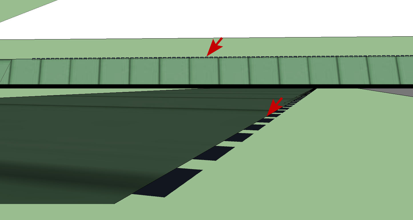
Also, you have many elements that are not co-planar. The attached image - set of dashed lines for example are not on the same plane. The dashes are lower than the rest of the roof and walls.
Note that small lines in SU will wreak havoc in a heart beat.
Another suggestion would be to create a large plane then draw your lines on it. Having a surface to draw your 2d lines on will help prevent snapping to some arbitrary point.
-
Great info. Thank you.
Is there a way to "lock" all of your drawing into the Z plane? Or move your points in the Z (or x or y, for that matter) plane? I know in ACAD you can draw the line, then alter its start and end point coordinates in XYZ, or just draw it by entering the coordinates. Or maybe an add-in to flatten everything into the same plane?
-
@unknownuser said:
Is there a way to "lock" all of your drawing into the Z plane?
@unknownuser said:
Another suggestion would be to create a large plane then draw your lines on it. Having a surface to draw your 2d lines on will help prevent snapping to some arbitrary point.
I think that is what drawing your sheet plane would effectively be doing. Each time you ad a line or other element you will get "On Surface" indication.
-
Boofredlay as an aside...if one is using 2D tools is it advised to mix in the standard textures rather than the 2D hatches?
-
Pete, I don't know of a way to lock your drawing tools to a z plane. One way to be more sure you are drawing on a single plane is to do it in perspective mode and continually rotate around your drawing. I don't use SU for 2d much so someone else might weigh in with a better solution.
As far as flattening your geometry when it goes South, you could use TIG's Flatten to Plane plugin:
http://forums.sketchucation.com/viewtopic.php?p=281320#p281320Michael, I am not sure I understand your question.
-
@unknownuser said:
Michael, I am not sure I understand your question.
I think that probably answers my question.

-
@mics_54 said:
@unknownuser said:
Michael, I am not sure I understand your question.
I think that probably answers my question.
Glad I could help

-
Pete, I had a bit of time at lunch so I did a quick video of how I would go about a 2d plan like you are showing. Hope this helps.
Draw a plane, group it, use it as a canvas, delete it then finish up your plan.[flash=853,505:32x4el71]http://www.youtube.com/v/Pmc-hJzqhl0&fs=1[/flash:32x4el71]
-

but one question...how did you do the line extensions when doing the intersections for the hips and valleys?
I dont get the inference.
-
Start your line, hover over the existing line then hold down shift. This will extend the line allowing you to reference another point on the drawing. Or start your line, move it along an axis and hold shift, again it will continue along that same path allowing you to reference another point.
-
dang it i knew that!
Hello! It looks like you're interested in this conversation, but you don't have an account yet.
Getting fed up of having to scroll through the same posts each visit? When you register for an account, you'll always come back to exactly where you were before, and choose to be notified of new replies (either via email, or push notification). You'll also be able to save bookmarks and upvote posts to show your appreciation to other community members.
With your input, this post could be even better 💗
Register Login


Advertisement