[Plugin] Hatchfaces (v1.8 beta) UPDATED 15-Dec-2012
-
Why not create two separate methods to handle the Z fighting based on what the user wants? If the user chooses just a hatch, then doing a 2mm offset would be fine and eliminate the issue with Z fighting. If it's a stamp, then make is flush and the explode/intersect should get rid of it. If the hatch gets put on it's on layer, it can be toggled on and off that way and won't interfere in general modeling operations.
-
@unknownuser said:
I think the cutting compo is best.
Let me 'sleep on' the best arbitrary-placed-group>>>cutting-compo ideaYeah, that sounds very nice, much appreciated. I think we give this cutting thing another go.
Meanwhile, I will work on solving the crashes with nested components. It's irritating business

Have to restart Sketchup everytime, after running the script.Eartmover. Thanks for your suggestions. I'm glad some potential users of this plugin is acctually responding, with requests and solutions. Your ideas will be Plan B. And what do you think about an option that the geometry explode on the face, as well (In case we go for plan B). As a modeling tool.
-
If it's a cutting thing you can always explode it when your happy.
I think that a Setting-Out-Point fro the hatching would be a big boon...
Still testing ideas on the whole cutting issue...
-
Here's how to make the group into a cutting component...
I know you've probably used different reference name but here I call the originally selected face 'face' and the group you've ended up with containing the trimmed hatching lines/faces etc 'gp' [Note a cutting components will make a hole the size of its perimeter edges so you need to remove any outer perimeters if you want a series of cut pieces... OR keep the outer perimeter equivalent to that of 'face' and make any 'un-hatched' areas of face within the hatching-group with the same material as 'face.material' so they look equivalent???]
` tr=Geom::Transformation.rotation(ORIGIN, X_AXIS, -90.degrees)
gp.entities.transform_entities(tr, gp.entities.to_a)it's made flat
tran=gp.transformation
tr=Geom::Transformation.rotation(tran.origin, tran.xaxis, 90.degrees)
gp.transform!(tr)it stands up but...
we have now corrected the axes to suit a cutting-component
now make it a component...
ins=gp.to_component
defn=ins.definitionmake it 'cutting'
defn.behavior.is2d=true
defn.behavior.cuts_opening=true
defn.behavior.snapto=0glue to the original 'face'
ins.glued_to=face
it now 'cuts holes' in the 'face'
now set names/layers/etc
for the definition and instance
defn.name='????????????'
ins.name='????????????'
ins.layer='????????????'
###` -
 X_AXIS, Z_AXIS, Y_AXIS. I've totaly missed those symbols.
You should see my code for retrieving the X axis comparison... Oboy, what a rookie....You know. In the API the examples use small letter for stuff like x.axis etc. I though they where aliases and not acctual symbols.

I like your code, nice and clean. This could work
 I have already put in the defs and behavior, so I only need to change the transformations.
It's only face who cuts no? Maybe that's what you mean.
 Anyway, that is the behavior desired.
Will try now. Thanks a lot TIG!
-
The group becomes a component, that component can glue/cut.
When you add an instance manually the face you snap to is taken as the face the instance will glue to.
However, in code the instance is just sitting there unglued on the face, so you must tell it which face it glues to with
ins.glued_to=face
Obviously the instance needs to be on the face to work properly, BUT in our code it is anyway so we don't need to move or transform it to suit - as we might with other less specific code... -
Hah! Sofisticated! That's why I did not see any translation.
I understand what you are saying, but must not you add a new instance to get the cutting behavior? Therefore translate as well to orirgin, and put on
an inverse transformation on the new instance?I'm not getting any effect. Could of course have made some misstake when I incorporated your code into my script, will doublecheck that.
Anyway, I will experiment a little with your code. I'm very happy with your rotation script. That's the part I was stuck on. Just had to put on a vector translation to get to origin(bounds.center to ORIGIN). Wonder if one could use that as inverse.transformation though?
On with the testing!
Thanks!
-
Even if you add a new instance in code it will not cut until you specify its glued face.
So just use the existing instance [the converted group] and glue that to the face, as it's already in the right place !!
Why do you need to change the transformations at all?
A group's definition is made at the ORIGIN etc no matter where it actually is.
The group itself can be adjusted using its transformation data like .origin and .xaxis....
Why do you need to involve 'bounds' ?? -
Ok forget about bounds for a minute.(I was using it's center as pt for pt vector_to ORIGIN).
Anyway since this did not work at first few tries, I assumed it had relvance with Sketchups behavior in native mode.
The cursor must be at the face to be able to glue to a face=NO transformation on entities.(You know this I'm sure) If you select the entities inside a component and translate them AFTER components been created.
Then insert a new instance, it won't glue to a face. In fact it will keep the distance from cursor and it's impossible to place it on to a face. You can move it after it's been placed though, but it will not then cut the face.
I provide some pictures to better illustrate what I mean.BUT! If you say translation is not needed. I believe you. You know more then me about this. Then I will continue to work with your code as it is. This is just a theory I had why it wasent working in the first place.
-
Well...
if not group.parent==modelthen you MIGHT have to use thegroup.parent.transformation.originandgroup.parent.transformation.xaxisinstead ofORIGINandX_AXISwhich are the model's equivalent - just experiment...Why would you want to place a hatch-component onto another face - it's custom trimmed to the one face ??
-
Ok, I will try that.
@unknownuser said:
Why would you want to place a hatch-component onto another face - it's custom trimmed to the one face ??
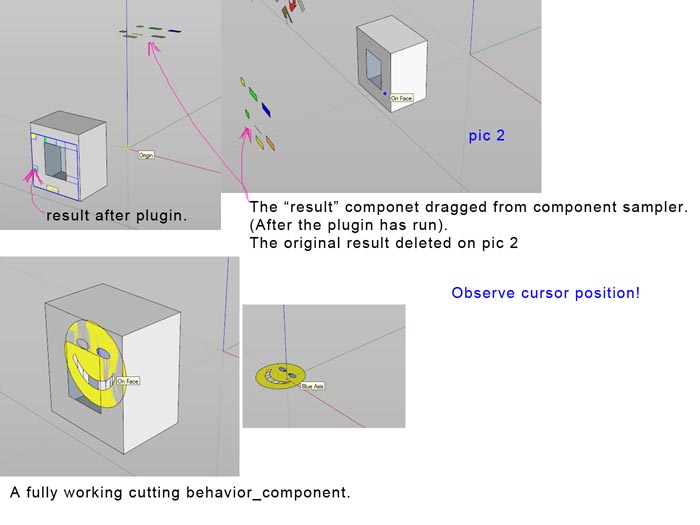
I don't want to do that. I was just dragging an instance of the "result" from component sampler to illustrate Sketchup behavior. To show where the "input point" was on the hatchcomponent.
I don't think we are far off a solution anyway, I will keep trying.
-
No Go

Using the exact transformation as you provided TIG. It stays in place as you said. AND the instance get glued to the face.
Even tried making a new instance from that definition + transformation. It has the correct position and glues to the face.
But no cutting behavior. IF you test and insert another instance from the component sampler manually, you can see the origin is off.The problem must be there? Don't know what else to think of. Behaviors should be correct.
My guess is.
- tr=reset group.entities transformations to origin(flat at 0). Don't know if have to multiply transformations to do that.
- Group.to_component.
- Make definitions.
- Erase instance.
- Insert a new instance with the inverse transformation of tr.
-
Are you sure the
defn.is2danddefn.cuts_opening = trueanddefn.snapto = 0
Test the defn to see what these are
defn.is2d? defn.cuts_opening? defn.snapto
should be true/true/0, and theninst.glued_toshould >>> 'face' -
The components you are using to compile the hatch-group contents, which will eventually become a component don't need any special behavior - you are adding these transformed anyway, then exploding them etc.
Only the new hatch-group that's to become a component-instance later needs transforming so if it were at the origin then all of its entities are transformed around the 'X_AXIS' so as to be flat within it - i.e. so the 'origin' then has the blue/Z axis sticking out of it. Once you've done that the original-instance [the group >>> component] is now seen to be at 90 degrees to where is was first made on the selected-face [its innards have been flattened], so you need to transform that instance about its origin/xaxis so that now it stands back up again, where it was before; but now of course its axes are turned to suit its new role as a cutting-component's. Theinst.definition.behavioris then adjusted so it glues/cuts/is2d=true and snapto=0, but at this point it is not glued to anything -inst.glued_to >>> nil- therefore you useinst.glued_to=faceand it now glues/cuts the 'face' as expected....... -
I'm confused too.
After you have added the smiley components and exploded them, then trimmed etc they will have lost their cutting/gluing behavior if they ever had it - which is not needed anyway...What you have is a group this is 'flat' on the originally selected face.
this group will have an origin given by Sketchup - usually at its bottom left corner - tis equates to the ORIGIN. Therefore we transform all of the group's entities - faces/edges using a rotation transformation centered on the ORIGIN around the X_AXIS and -90.degrees...
If the group.parent != model we take the group.parent.transformation.origin and .xaxis instead ???
At this pint we have the group laid flat with the same axes.
We rotate-transform the group about its .transformation.origin and .xaxis and 90.degrees... so that it stands back up with its axis now so the blue axis out of the face.
Make it a component, change that instance's definition.behavior to glue/cut etc etc and then tell the instance it's .glued_to-face ???I keep repeating this in tests without problems?? You show me images of the thing before that's cutting when it shouldn't be etc...
Are you sure you are using the right code/references etc... -
@unknownuser said:
I keep repeating this in tests without problems?? You show me images of the thing before that's cutting when it shouldn't be etc...
Are you sure you are using the right code/references etc...Before smiley is an original. It's a component with cutting behavior.
I'm not sure I'm using the right references. I've tried changing them back and forth a little. It's no big change. My group is called gp.2 and transformation tr4. The thing is I have altered the smiley comp several times before the plugin is about to do your provided rotations. Exploding, entities add to group, intersection, edge removals etc. Maybe I've gone wrong somewhere there, and the axis is off somehow. I will have to do some more tries.
But if you look at the last picture, the blue model axis IS pointing in the face.normal direction. Which is good?I thank you for your help in this TIG. I have difficulties understanding transformations in code. I thought I got it, but It seams not

Just a theoretical question. IF one would move the group to Global origin, one would have to rotate around each axis no X,Y,Z? To be sure to cover all angle variations.. Hope you understand what I mean.
I will do some more tries, and also see if I have put in your code wrong. -
Deliberately testing off origin and it works for me
-
@unknownuser said:
Deliberately testing off origin and it works for me
Yeah, that was a desperate long shot, assuming you did not think off that
.Ok, so now I guess I'll have to pinpoint what goes on with the geometry at each step, that would different than in your model.
-
Select a face in the model, in the Ruby Console type or copy&paste
face=Sketchup.active_model.selection[0]to get a reference to it - we'll use it later.
Make a standard piece of hatching on that face [it needs to be smiley face type in a group] with no attempt at make it a component, or glued or cutting in code.
Select that group, in the Ruby Console type or copy&pastegroup=Sketchup.active_model.selection[0]to get a reference to it.
Now run the individual lines of code one at a time on that 'group' - see it's changes.
It should eventually become a component that glues and cuts and is attached to 'face'...Repeat with a face inside another group.
See if it fails - if it does then try changing the code for the transformation used in the initial group.entities.transform_entities() to the 'parent' version I gave. If that part succeeds but the later instance transformation fails try using something like (group.transformation*parent.transformation).origin etc instead... -
Thanks TIG. I've acctually just done something similar.
Although with the smiley exploded.I will try your method as well.
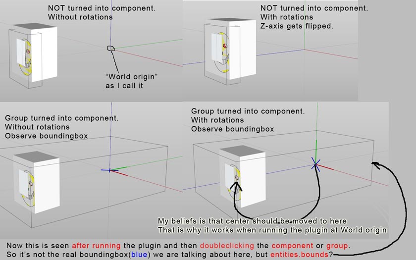
What I have discoverd so far is that when turning group to component.
ins=gp2.to_component
The center of component.entities get to world origin(you follow my explanation?)
(I see this if double clicking the component and the axis are shown. PIC)**This happends with or without your rotations.**Your rotations flips the "blue" axis in the face normal direction, wich is what we want, right? So thats good.
But in order to make the cutting work in think one must move the component.entities center to the face, can't explain it better..
That's probably why it works when I'm doing test at ORIGIN.In short! It doesent look like something fishy is going on with the geometry UNTIL turning group to component.
Elaborating with group.transformation*parent.transformation might be a good idea. Cause this problem has to do with transformations. The glue to face is working.
Hello! It looks like you're interested in this conversation, but you don't have an account yet.
Getting fed up of having to scroll through the same posts each visit? When you register for an account, you'll always come back to exactly where you were before, and choose to be notified of new replies (either via email, or push notification). You'll also be able to save bookmarks and upvote posts to show your appreciation to other community members.
With your input, this post could be even better 💗
Register Login


Advertisement