[Plugin Request] - Minimal-wall-thickness test for 3D-Prints
-
Hy,
i just had rather unpleasant experience. I uploaded a model of mine, designed and checked thoroughly by the magnificent scripts hosted here on this site, to shapeways last week and after it was accepted. I ordered it. And today i get an email that they could not do it because i did not met the requirement of the minimal wall thickness and therefore can not produce my model. So my problem is, that i have combined several small part models into one to save on setup price for Frosted Ultra Detail material. So not only do i not get one model, but i do not get said several models... And i am also lost at finding the problem in there since a seperate upload of the single models will also be accepted me thinks! So what i need is a way to find such problematic areas by some kind of checking plugin that asks me for minimal wall thicknesses and shows me the parts that i have to look into. I can provide the model and any kind of moral support, but i can not program to save my live, sorry

Can some kind heart take on that mission? I think it could be of greater interest since there are more and more people into 3D-printing.
Thanks in advance
Flashhawk -
hi
can you post an image [or file] to give some clue as to what you [or others] might do...there may be simple steps
john
-
Sure thing. I added the file of the most suspicious model. Somewhere in there is a place to small to reach (at least for a 3d printer
 )
)
Thanks
Flashhawk
-
Have you seen Cadspan? I think it does what you need.
Its best practice to know what the minimum wall requirements are for the material you are 3D printing in, then design your model around those requirements. I've modeled several designs that were successfully printed via Shapeways, so I can help you further if necessary.
-
in your drawing, a couple of faces are reversed, it may be that,
some cam formats would fail that as being non-manifold...
I'll have more of a look tomorrow.
john
-
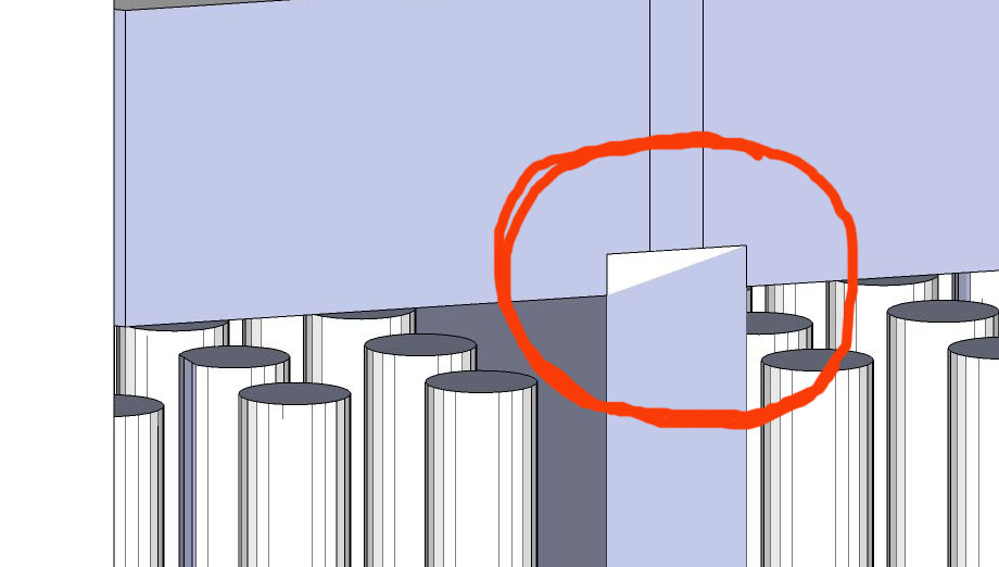
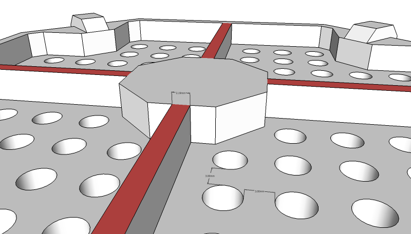
I believe I found your problem, which I've shown in the area highlighted with the dimension below:
The 'legs' connecting the top and bottom potions of the model are too thin. The minimum wall thickness for Frosted Ultra Detail material is 0.3mm, and the design is at 0.2mm. However, from my experience knowing that FUD material is somewhat brittle, I'd even increase the thickness to a minimum of 0.5 - 1.0 mm thick, because the weight of the rest of the model above may be too much for even 0.3mm.
Also as John mentioned, its best to correct face orientation - its easy, just right click one of the white faces -> Orient Faces.
One last thing I noticed (which may or may not be causing printing problems) is this minor detail illustrated below.
-
Of course if there was a plugin that could check for wall thickness (the user would set the minimum to check for based on the 3D print material requirements), the process would be much faster...anyone?
 Is it even doable?
 -
Unless I am mistaken, everyone has missed the problem. Major parts of your model have no thickness at all. It is hard to describe, but when I "fly" into the model from the bottom vents I can see the tubes (or holes as seen from the outside). Then I approach the tubes and remove the bottom surface and I should be trapped by a second wall. Instead, I can travel up the tube and back out into "outside" space. Every surface in the model has to be double walled and it is not. Think of every shape as a container for poison gas which must be segregated from pure air on the outside. No wall can have either pure air or poison gas on both sides and separated by a single surface. The model is simply incorrect for 3D printing. You have many walls with zero thickness.
-
I think you are seeing it wrong, Roger - think of the cube as solid and those holes have been drilled out from the top. The original model is made pretty well, in fact Sketchup does show the original model as being solid...it just needs some minor modifications to work within the constraints of real-world materials.
-
Ok.. since Shapeways does not understand skp files, i usally upload in STL format. And as i said i could upload it and it was not rejected.(so reversed faces seem not to survive the stl-export) The initial check for solidity was confirmed. But when they actually started to produce it, their machine told them it was not possible because of the wall thickness issue. As of now i think d12dozr is right with the thickness of the legs there, although that they are no legs. Thes pylon keep the firebreach plate at a distance to the back of my [H]eavy-[L]ong-[R]ange-[M]issle-Thrower for Battletech
 so they do not need to support the weight, thats what i ment with this explanation
And i must say i checked the Model from all directions (in and out) Roger and can not find any missing walls... maybe you up a pic or so? I test all my models with solid inspector and cleanup³ so there should be no issue, but you never know And of course i think a wall-thickness-checker could be great thing. I would add the idea of a optional material change to the wall other than the circle-thingies from solid inspector which disappear when you work on the errors. One could reverse the material afterwards by button or so.. but no, when you changed the model for greater thickness you possibly do not have the same faces to color... but you could a have button that stores a couple of materials on a flyout so that you could grab them and put them back were you need them... Ok these are just ideas for people that are into full-color-sandstone, because i dont use any material or color at all as you can see in the model...
And thank you all for the tips!
Flashhawk -

Check this area for funky (Technical term) coplanar problems.
-
hi
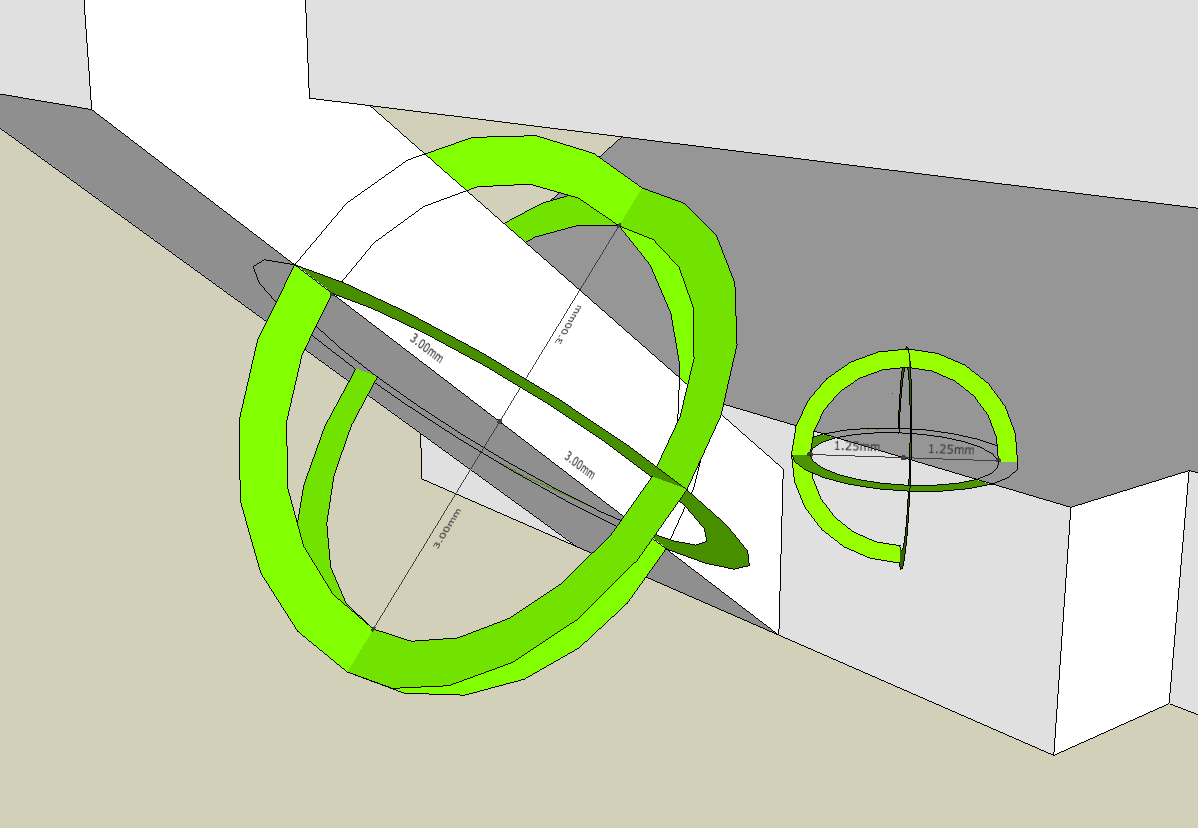
I marked a couple of things, this ones not mentioned yet, if 3mm is your limit.

I think a ruby to check something as simple as this would be difficult, but if you make wire type structures it would be nearly impossible...
john
-
John, those are considered 'details' - which have a minimum of 0.1mm in FUD - since they are connected to thicker walls, so they should be OK.
-
@d12ozr the devil is in the detail...
a gizmo, not unlike this component I just made might be useful.

you can scale this within itself using the 'tape tool' then 'rotate' to match the angles of the face.
but, if it was a gizmo it could be set/re-set via the input box and aligned like the rotated rectangle tool [pick three points]
oviously, this is still a manual job, but it could be easier than trying to align the dim or tape tool, maybe...
john
-
Yeah, that gizmo could be useful for checking existing models if it was easy to orient - like you said, still pretty time consuming for large models.
-
I think this does what you want http://forums.sketchucation.com/viewtopic.php?p=346362#p346362 'TIG.colorthinfaces'...........
If you want it to skip small curved surface facets it'll take more coding...
These can be ignored and re-colored anyway. The problem is that a small facet might be ignorable but the total assembly of then might still not be thick enough ? For example a think cylinder would pass if the smoothed faces were below the limit, BUT it ought to fail as its cross section is too small anyway ??
Trying to consider all connected faces is not workable either because a solid has all of its faces connected anyway
I suppose if we find such a face below the size limit but smoothed we can look at all of the faces that share its edges ? Then if the angles between the face and any of its neighbors is less than say 30 degrees [internal-convex] it fails. Otherwise it's assumed to be on a 'surface' like a cylinder/sphere/mesh... Now to think of how to code that...
Advertisement


