Shapes quite often fail to make faces capable of push/pull
-
Hello,
I am very new to sketchup. I have been working on a floor plan, and using the Curved Line tool to draw a lot of my curved lines (imagine that!). I have a floor plane, and on it, I draw all my lines, then I select the interior of those lines and push/pull. However, a lot of the time I find it doesn't work, and I resort to, what I consider, ludicrous things to get it to work, such as drawing various straight lines within my shape, then erasing them one by one... sometimes this alone works... sometimes I need to have a little bit of a space and the rest of the shape is fine... I guess it's kind of hard to explain, and it really seems like there would be a space between a couple of my lines, but I really don't feel like this is the case. If I draw a square I have no problem pushing and pulling... but, when I draw my curved lines, i'm clicking on an end point of an existing line when I start drawing, so, I don't understand how there could be a space.
Can anyone help me out here? I'm really confused. Thanks.
-
Hi Taosd (and welcome).
As you figured out, the edges must create a closed loop in order to form a (PushPull'able) face. Not this is the only condition however but also they must lie on the exact same plane (i.e. they must be "coplanar"). Often, when working with various line tools (especially the Freehand and Arc tools), one can very easily get out of this plane. One way (that you actually "practised") to find the glitch is to connect opposite edges/endpoints until you find where the problem is.
A face can be prevented from forming also if there are (even the smallest) "stray lines" "poking inside" from the outer corner.
Best would be if you uploaded an example file with this problem (find the "attachment" tab under the text area you are posting) so we can have a look.
-
Hi Gaieus,
Thanks for the warm welcome. Attached is a sample of the floorplan I am working on (We will focus on the one closest to the origin, the left most one). If you look at the arching area in the middle of the floorplan, it looks to be sectioned off, but I cannot raise it. I really appreciate your assistance.
-
Ehm... The attachment?
As for the arc being sectioned; every curve is sectioned and every curved surface is faceted in SU. You can set the segment number higher or lower (to make it look smoother or have the model lighter) but there will always be segments/facets.
Edit: re-reading your (and my) post, I may have misunderstood that "sectioning" for "segmenting". The file would be useful.
-
-
OK, I see the problem. Was trying something but got a nice bugsplat. Will experiment more. The curved lines seem to be coplanar though.
-
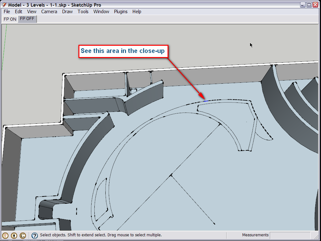
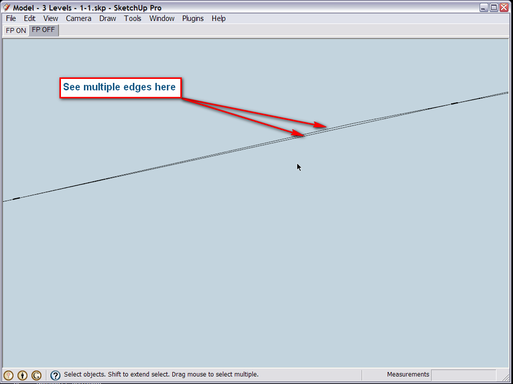
Well, as I made one of the "guesses" above, there are numerous "stray lines" there. Many of the edges are doubled (or even tripled!). See this bigger view and then the close-up.
You'll definitely need to clean up the model for this to work.
-
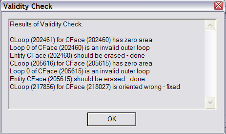
It's definitely a buggy model, I have to say. It took quite a while to fix (in the meanwhile, I made a couple of "validity checks" [Window > Model info > Statistics & "Fix problems" at the bottom] and got these weird results attached - and even at the end, on saving, it reported problems).
Here is the file "more or less" fixed but I'd rather re-do the whole inner area instead because it may still give you headaches. I also reversed many of the faces so that now the white shows outside but not all.
-
What CAD program created the original model, and how was it imported? My guess is that it may be easier to go to the original program, and close all lines, then to fix it in SU. If you think that the original model is good; coplanar, and all segments joined, it could be the export function of your program that is not accurate. If you are using ACAD, native or DXF, then the problem is in the drafting method used to make the original drawing. If that is the case, in the long run, unless you change your drafting procedure, you will continue to have problems. One way to avoid the problem with unclosed line segments, is to draw the original line as a polyline, or to loft it into faces (surfaces) before porting to SU.
Attached is a DXF made of 3 arcs, that were extruded into polylines along the z axis as faces (surfaces) then converted to dxf. Rename the file Temp.txt to temp.dxf then import it into SU and you will find a curved wall.
Btw: to any admin person. Why can't I upload a DXF directly? Especially since it is nothing more then a text file.
-
wow! I really appreciate your level of assistance! What could you recommend to prevent the model from having a bunch of issues on it in the future?
-
Well, if you import CAD drawings, be very careful as Honoluludesktop suggested above.
If you draw straight in SU, well, also be careful.

Here you must gave used the arc tool several times on top of each other (I guess) or something like that. There are a bunch of really great curve drawing plugins; they can also help. -
hmm... i did import from autocad 2009... strange. oh well... Thanks for your help.
-
Hi raosd, If you are importing a native ACAD file, then it must be the a problem in the way you are creating the original drawing. Make sure that when you draw, the line segments are trimed together. If however you are certain that your ACAD line segments are joined, then I don't know what the problem is, unless it is SU, but if this were the case, I would expect that other users would have mentioned it before. There is a way to test this but it is very involved, and requires that you save to dxf and look at the raw line segment data.
Sorry for questioning your sincerity regarding this post, but you have not even bothered to download the files that were created, and posted for your benefit. If you had, and the admin. program is at fault, please except my apology.
-
Hi HonoluluDesktop, I hadn't downloaded the files yet, but I have now. I was busy and didn't get a chance to download and check out the file until now. My apologies.
Hello! It looks like you're interested in this conversation, but you don't have an account yet.
Getting fed up of having to scroll through the same posts each visit? When you register for an account, you'll always come back to exactly where you were before, and choose to be notified of new replies (either via email, or push notification). You'll also be able to save bookmarks and upvote posts to show your appreciation to other community members.
With your input, this post could be even better 💗
Register Login


Advertisement