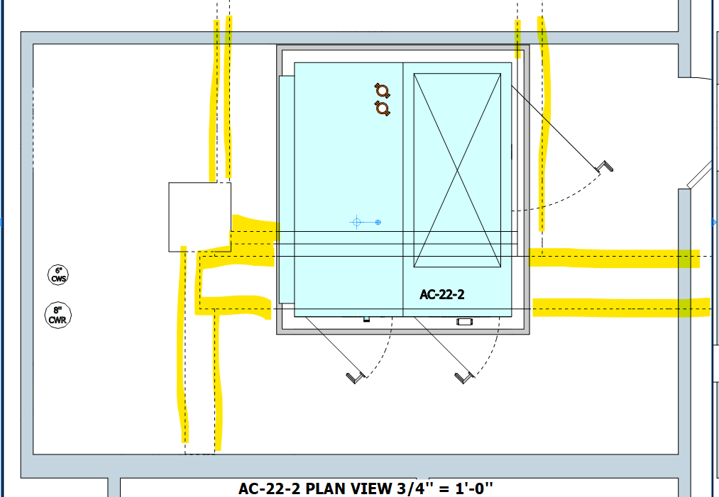
Unwanted dashed lines in viewport
-
In layout 2024, solid edges in the model are sometimes represented as dashed lines in the layout viewport when the viewport is set to hybrid or vector. But only if those solid edges are in an object that exist above another object in the model. Changing to raster worsens the problem. Attached image is vector. I assume this is a bug.

-
@pipingguy Share the LayOut file so we can see what you've got going on. What version of SketchUp/LayOut? What operating system? What graphics card?
-
hi Dave
SKP/LO version is 24.0.484
video card is Nvidia GeForce RTX 4070 Ti
OS = Win 11LVL 22,23,24 [sketchucation].skp
[LVL- 22,23,24.layout](Invalid file type. Allowed types are: .png, .jpg, .bmp, .gif, .pdf, .rbz, .skp, .obj, .fbx, .dxf, .dwg, .mp4, .mov, .txt, .zip, .rb, .jpeg)
-
why is my lo file un-uploadable??
-
@pipingguy Try to upload now please
-
@pipingguy I see what the problem is from your SketchUp file. I'll be back.
-
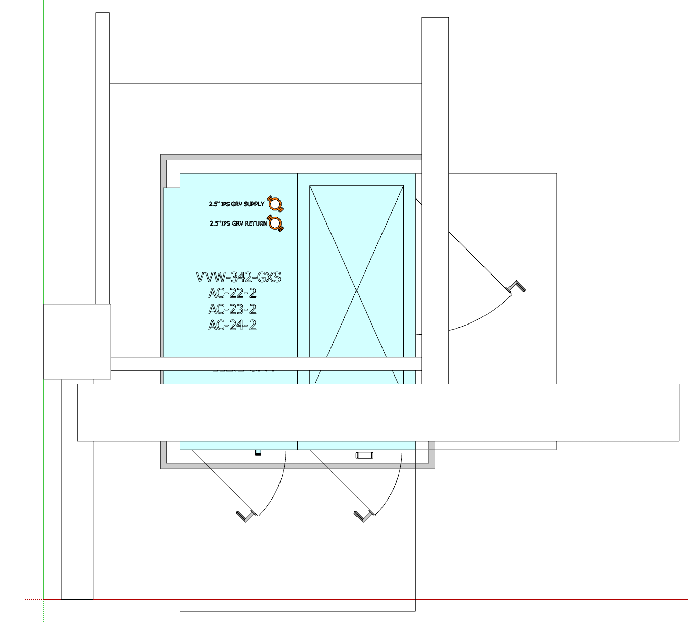
@pipingguy so the dashed lines in your file are basically the same as z-fighting which occurs when two face share the same place. Yyou've set up your model so the side faces of the beams are viewed edge on and in the 2D viewport that put the bottom edge and the top edge in the same place.
TBH there are better ways to set this up. I copied the geometry of interest out of your model and into a new .skp file. I simplified the beams so each one is a sold object the way you would model them in the first place; just boxes. I also removed the tag for the beam top and bottom faces as you don't need to complicate the model that way. I also removed all dashes in SketchUp. The scene in SketchUp looks like this.

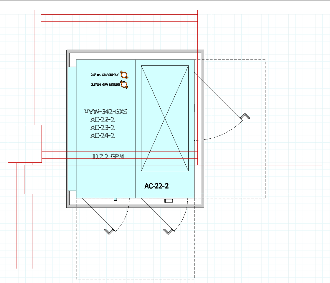
After sending to LayOut, I set up the viewport to the desired scale on the page and rendered it as Vector. I added a second layer on top of the Default and copied the viewport to that layer. (Copy, Paste to Current Layer).So now I have two copies of the viewport stacked on top of each other in perfect alignment. For the top viewport I turned off all the tags except the one called "BEAMS AND COLS". I also set the style to Hidden Line. Hidden Line with Vector rendering means only the visible edges are displayed. No z-fighting of edges, either. To create some contrast I also set the edge color for the beams and columns tag to red. Of course you do what you want with that. You could show those lines with a different dash style.
For the bottom viewport I turned OFF the tag for the beams and columns and left the others turned on. I set a dash style for the door swing arcs and another for the clearances which I tagged separately.
In LayOut, then, the view looks like this.

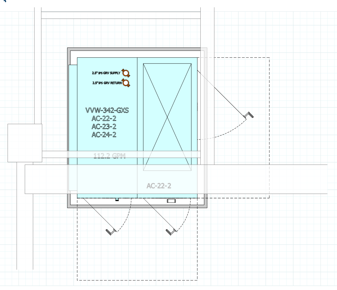
While I was screwing around I made a different version in which the style for the top viewport has Shaded or Shaded with Texture face style and Xray enabled. In the viewport I set the edge color for the beams and columns to gray. So it looks like this.

Here are the SketchUp and LayOut files.
PG.skp
PG Example.layoutI find it easier to manage dashes in LayOut and never set dashes for tags in SketchUp. I also created a collection of different styles to use in LayOut projects which select for individual viewports as needed so my SketchUp model only has a single"working" style. I would replace all the 3D in the model is labels and text in LayOut. If you made the various units as components instead of groups, you could add the required identifiers such as AC-22-2 in the description field and then auto fill the text in labels. This would give you nicer looking text and make it simple to place it in a spot that makes it more easily read. Annotations like that would go on a separate layer higher in the Layers list than the viewports.
By the way, if you would control tag visibility for viewports in LayOut you could manage with a single scene in SketchUp for all of your plan views in LayOut.
-
@Gábor OK......now i can apparently upload it. What did you do?
-
@Dave-R Nicely done sir!!
Yes, I know my beam layering scheme seems like overkill, but there is a method to my madness. It allows me to quickly spot if any of my horizontal piping is penetrating the bottom of any beams while in plan view during pipe placement in the model. We generally need to hug the beams so as to minimize conflict with other trades. Looks like I need to simplify as your narrative suggests. Thank you for taking a thoughtful interest in this matter.btw - how did you know those outlines projected from the unit represent "clearances"?
-
@pipingguy You might consider creating an object with copies of the bottom faces of the beams that you can "put away" when you don't need it. You could even set up a scene in the model that shows the object for when you need to test for collisions or at least create a viewport from your plan view scene with the beams turned off and the bottom faces of the beams shown.
-
@Dave-R That's true.
-
@Gábor OK......now i can apparently upload it. What did you do?
@pipingguy Sorry for the delay in replying. I wasn't around the computer. I added the .layout extension to the allowed extensions.
Advertisement


