Component orientation
-
I have been modelling a part of my central heating system and found that orientating components to pipe runs can be a bit of a slow process. Each component can be set-up to have a convenient insertion point (Component axis) but a succession of moves, rotations or 'flip along' is then needed to position the component to the pipe run. In the case of a 90 degree elbow that could be one of (sixteen?) variations.
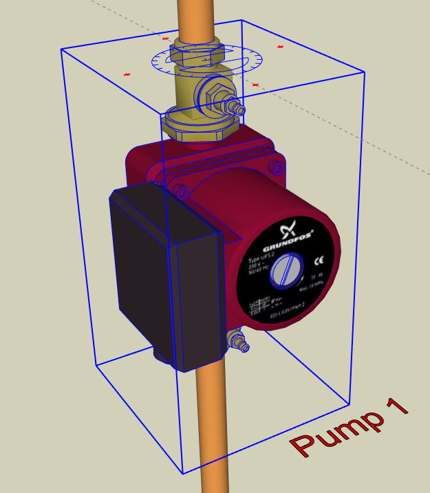
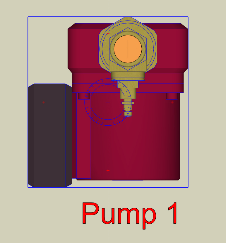
In the first two screenshots a generic pump is shown with it's selection bounding box and move compass. It's insertion point is the centreline of the valves. If the pump is now rotated using the move compass the valves will move away from the vertical pipe centre.
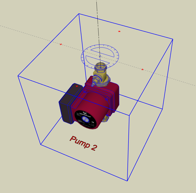
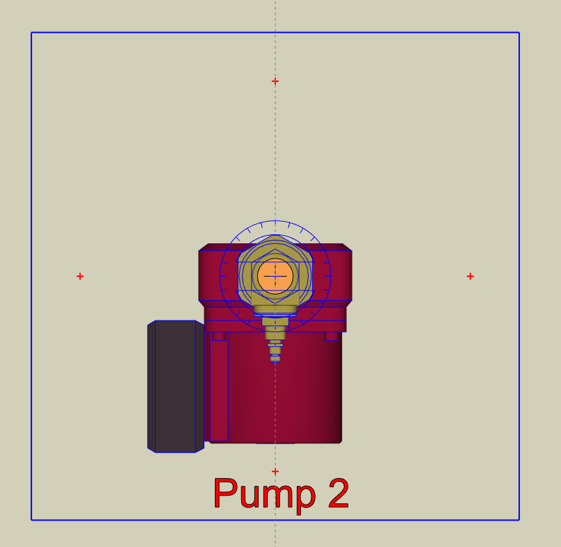
To make adjusting the pump position easier I have placed hidden planes within the component. I used squares but circles would work as well. The hidden plane should overlap all the other geometry and be centred on the point of desired rotation. The next two screenshots show the same pump with a larger bounding box and the move compass centred on the pipe centre.
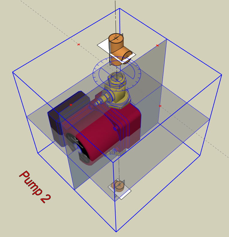
Lastly, a screenshot of the pump with the planes unhidden plus a couple of pipe fittings with the same process applied. Using this method the component can be rotated into alignment with the pipe using just the move compass. In essence, the hidden planes force the centroid of the component to be where the axis of rotation are the most useful.
Also, I attach a SKP (version 2015) file with the pump and pipe fitting components to try out as it will probably be easier to work with than my written explanation! I hope this may be useful and, of course, apologise if the idea has already been thought of and submitted.
Regards to all.
-
Just realised that the insertion point (Component axis) of the pump should have been set at the mid point between the two valves. Revised SKP attached.
Hello! It looks like you're interested in this conversation, but you don't have an account yet.
Getting fed up of having to scroll through the same posts each visit? When you register for an account, you'll always come back to exactly where you were before, and choose to be notified of new replies (either via email, or push notification). You'll also be able to save bookmarks and upvote posts to show your appreciation to other community members.
With your input, this post could be even better 💗
Register Login


Advertisement