Medeek Electrical
-
Version 1.0.3 - 04.03.2019
- Added an advanced option for outlets to display the outlet height with the 2D symbol.
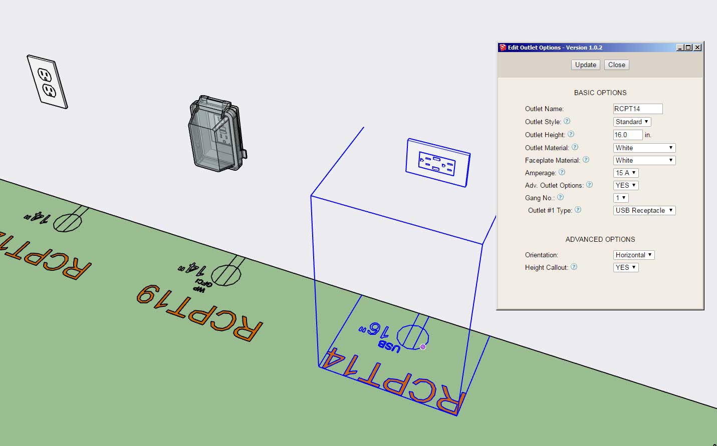
If this advanced option proves popular I can also add it to switches, low voltage outlets, safety devices (wall mounted), and light fixtures (wall mounted).
This advanced option is per customer request.
On my own electrical plans I typically don't call out the switch or outlet height however in some cases I have provided a height call out with GFCI outlets installed in the garage.
-
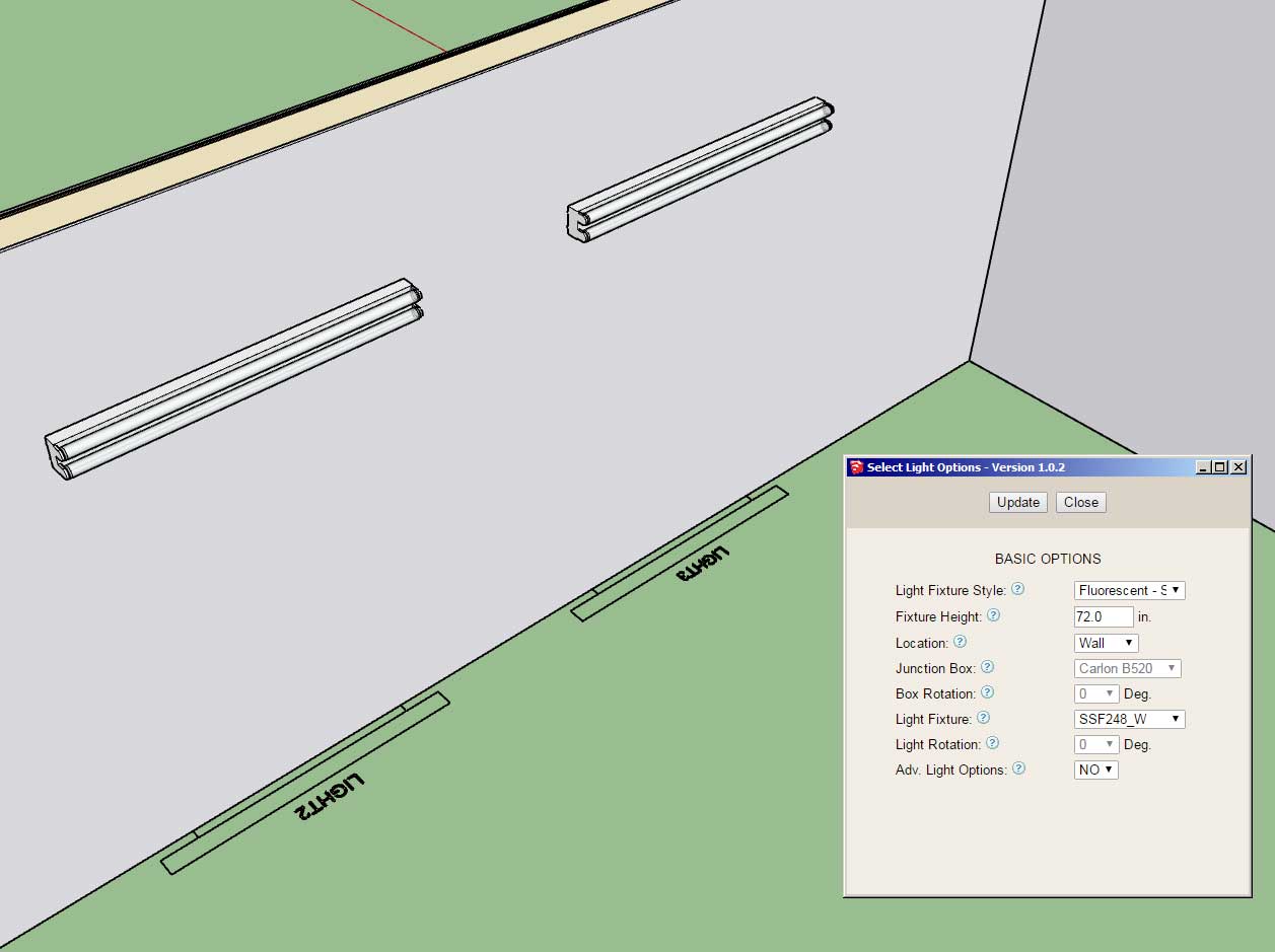
First look at wall mounted (surface) fluorescent light fixtures:
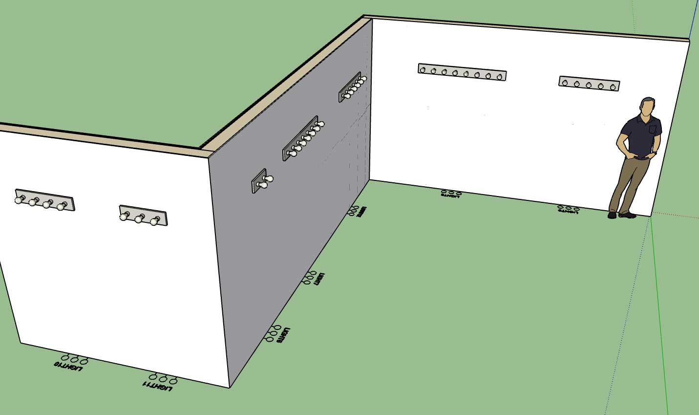
First look at vanity light fixtures:
-
Version 1.0.4 - 04.06.2019
- Added the following light fixture categories and symbols: Surface, Recessed, Vanity, Ceiling Fan, Ceiling Fan w/ Light, Fluorescent (Surface Mount).
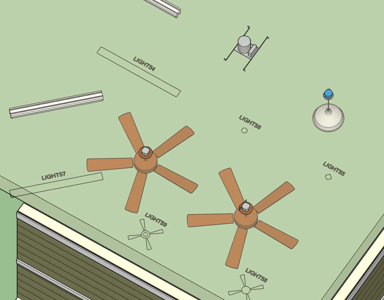
Now that I've reworked the light fixture module it is much more conducive to adding in additional light fixture categories/types, at some point I may even allow the user to add in custom categories. I still need to add in the fluorescent suspended and recessed categories and their corresponding symbols. However, I usually won't add in a category until I have a minimum of one default fixture to place into the library for that category.
-
Version 1.0.4b - 04.07.2019
- Added the following light fixture category and symbol: Fluorescent (Recessed).
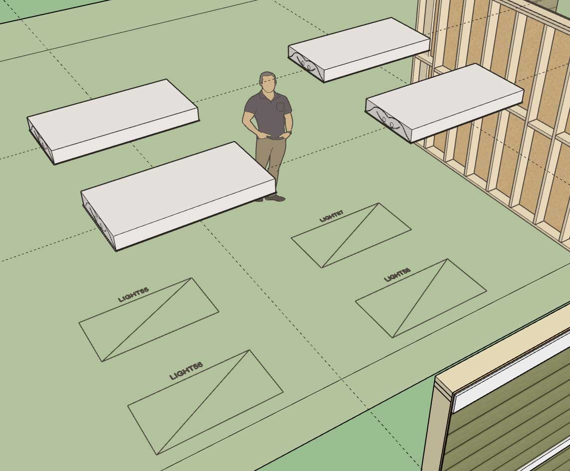
Included fixtures are a 2x4 and 2x2 troffer.
-
Version 1.0.4c - 04.08.2019
- Added the following light fixture category and symbol: Fluorescent (Suspended).
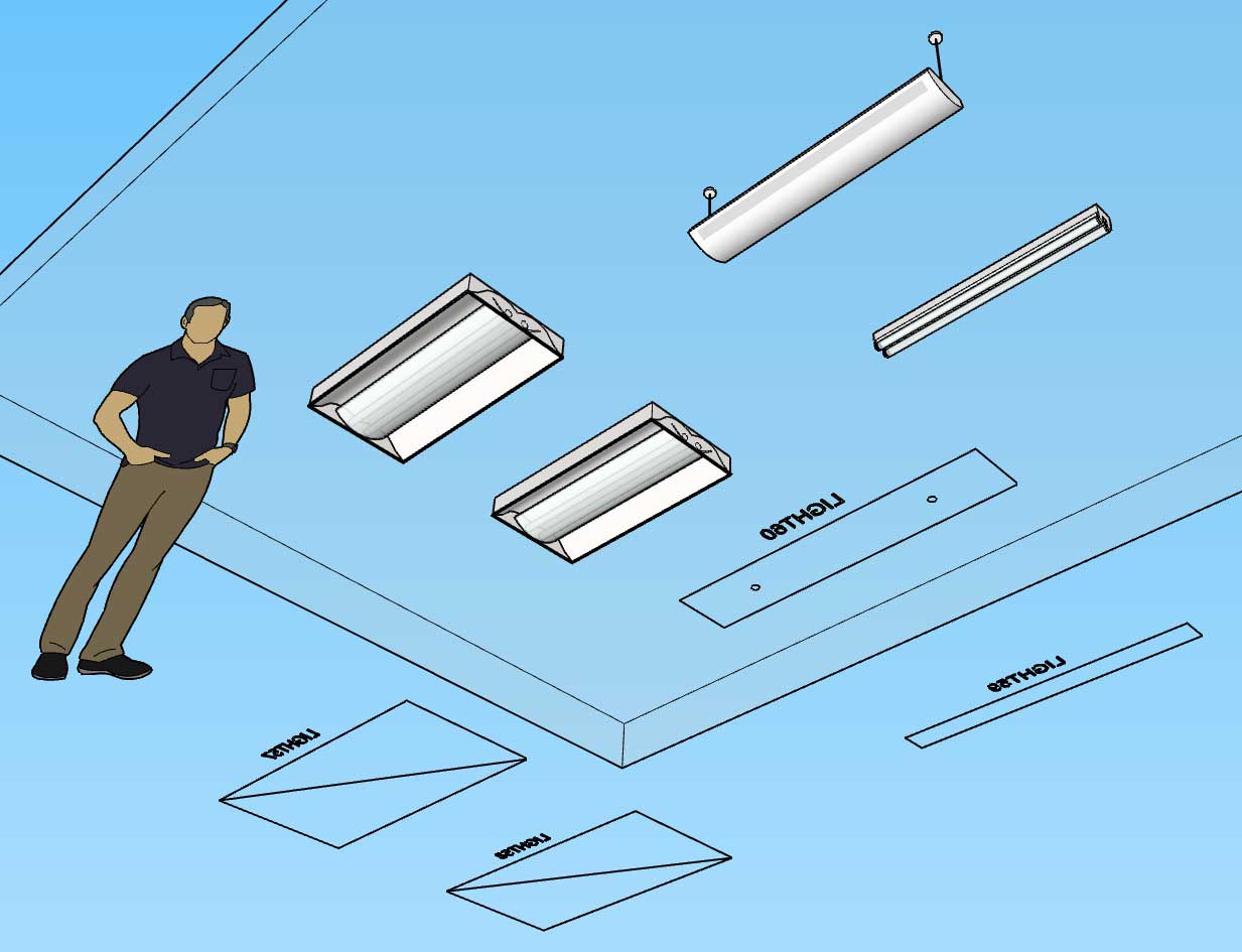
The only other major type of lighting that is missing is track lighting and possibly some variants of existing lighting types that indicate they are LED rather than fluorescent or incandescent.
With fluorescent lighting there is a small text file in each library sub-folder that specifies the dimensions of the light fixture. Technically the numbers for each light fixture can be set to any value (width, depth, length), they are only used to provide the wireframe preview and help with the placement if you toggle the fixture justification. I will put out a tutorial on how to use these config files and setup your own custom fixtures.
-
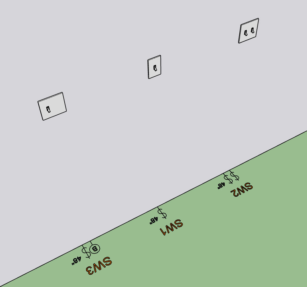
There seems to be a demand for the height callout next to the various electrical devices so I'm working at adding it to all wall mounted electrical devices.
First look at the height callout for switches:
-
Nathaniel, maybe you should create a mechanism whereby the end-user can format their own symbols according to your method? So I can have my own custom models (and variety) but how they are structured needs to conform to your methods to work flawlessly with your extensions. You can keep your examples in there, for reference or if end-user doesn't want to go through process of creating their own.
-
Version 1.0.4d - 04.09.2019
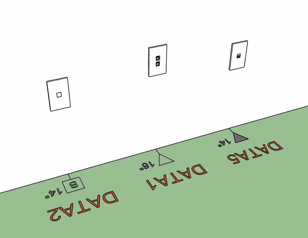
- Added an advanced option for switches and low voltage outlets to display the device height with the 2D symbol.
-
Users can already create their own models for certain fixtures and then simply upload them into the appropriate library folder. For example there are currently nine sub-folders within the light_fixtures sub-folder:
ceiling_fan
ceiling_fan_light
fluorescent_recess
fluorescent_surface
fluorescent_suspended
recessed
surface
suspended
vanityThe user can put as many pre-configured *.skp files into these sub-folders as they like and the plugin can then utilize them.
Each of these light fixture types entails a specific 2D symbol which the plugin provides. Also the categories currently cannot be altered or added to. In the future I may devise a system whereby the user can add new categories for a device type and also their own custom 2D symbols, I'm just not there yet.
-
@medeek said:
Also the categories currently cannot be altered or added to. In the future I may devise a system whereby the user can add new categories for a device type and also their own custom 2D symbols, I'm just not there yet.
this please
-
Version 1.0.4e - 04.10.2019
- Added an advanced option for wall mounted light fixtures to display the device height with the 2D symbol.
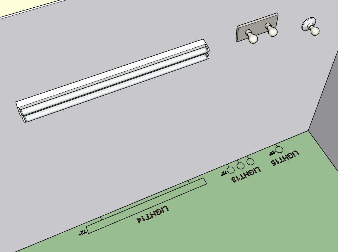
I also resolved a minor bug with the placement of wall mounted light fixtures so I highly recommend upgrading to this latest release.
-
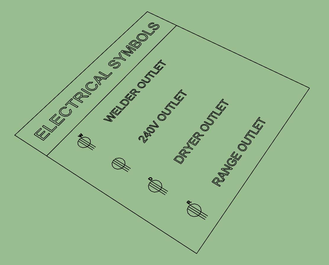
First look at the electrical symbols legend generated by the plugin:
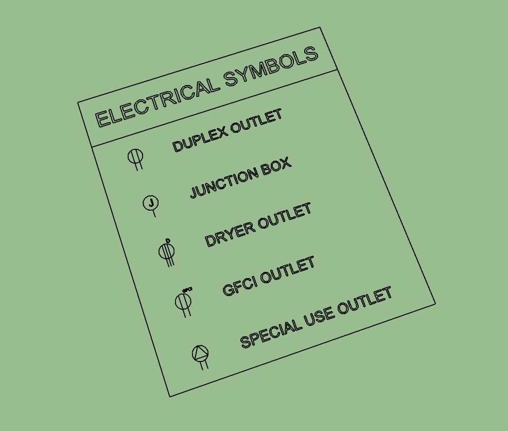
The secondary toolbar has the icon for generating the legend:

The legend is parametric so every time you click the legend icon/tool it regenerates the legend based on what electrical devices are present in the model. You can also move (x, y or z) or rotate the legend and it will retain these new coordinates when it is regenerated.
Initially the legend is drawn at the origin but can be positioned at any location (and retained) by the user using SketchUp's native moved or rotate tools.
The overall size of the legend and its text and symbol size is driven by the parameter in the global settings, as is the font of the text which will match the font used by the electrical symbols in the model.
It also appears that you can use SketchUp's native scale tool to scale the legend and it will also retain this setting when regenerated.
-
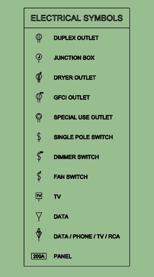
Outlets, Switches, Low Voltage and Load Centers.
I still need to add in lights, safety devices, Heaters and Vents.
-
Version 1.0.5 - 04.12.2019
- Added the "Draw Legend" function to the secondary toolbar.
- Enabled the ability to automatically create an electrical symbols legend for all electrical devices within the model.
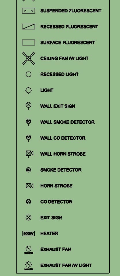
After working my way down through the list of possible symbols I'm surprised to see that there are so many and the legend can get quite large.
-
I think the real power in this plugin is not the ability to insert 3D components into your model, technically you don't even need a plugin to do this, just a bunch of pre-configured components (.skp files). The real strength is the automation of the 2D symbols and the parametrics of the plugin (allowing you to swap out devices types, colors, height and rotation). Now with the addition of a parametric symbols legend it automates yet another tedious task.
I'm fairly happy with the way the legend has come out but for future work I may include a parameter in the global settings which allows the user to enable sub-titles (divides the legend into logical sections: outlets, switches, lights, etc...) as well as specify the number of columns that legend should be divided into, this becomes more of an issue when there are a lot of electrical symbols to display.
I think some people would argue that I go too deep with my plugins (too many settings, parameters, options etc...) I would agree that if possible simple is often better. The goal is to make everything as simple as possible, but not simpler.
On the flip side the addition of more options and parameters increases the amount of data or information that model contains and hence makes it more useful (BIM). Options also allow the user to further customize their workflow with the plugin and tailor it specifically to their needs. Many of the options I have added have been directly requested by users of the plugins
-
For those that are interested I will explain how the new "Draw Legend" tool works under the hood.
First the plugin finds all of the groups in the model (active_entities, if no group or component is open for editing then this will be the same as entities at the root of the model).
It then checks inside each of these groups and identifies the electrical groups that belong to the plugin (based on the group instance name). Once it has collected up all of the electrical groups in the model it then divides them into their appropriate categories: Outlets, Switches, Light etc...
It then examines each sub-category and dives into the attributes library for each electrical device (group). The attributes library tells it what 2D symbol is associated with that particular device. It then creates a new list of symbols to draw for the legend for each category at the same time discarding or preventing duplicates.
The symbols shown in the legend are drawn, for the most part, using the same methods as the symbols drawn for the actual devices however some of them have been altered slightly in order to customize them specifically for the legend.
As you can see there is quite a bit going on under the hood. When a model gets large with hundreds of walls and possibly hundreds of electrical components generating the legend may take up to 30 seconds.
-
Version 1.0.6 - 04.15.2019
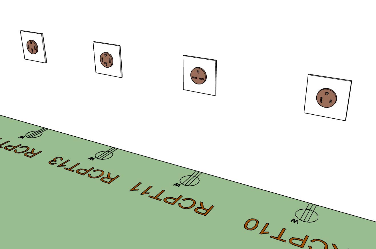
- Added additional NEMA 240V receptacles into the Outlet module: NEMA 6-30R, NEMA 6-50R.
These additional receptacles (and symbols) were per customer request.
-
Tutorial 3: Electrical Symbols Legend
-
Since adding the symbols legend I've had a number of requests for a tool to draw a schedule (similar to how I am drawing the legend).
Now that I've got a fairly solid routine for pulling the electrical data (I will use much of this same code for the estimating tool) it isn't too big of a leap to draw a schedule.
My question is what information do you need or want in this schedule, how do you want it laid out? Every device listed with its parameters or do I group like devices?
Please give feedback in this regard. Also feel free to send me any sample electrical schedules that I can utilize as references.
If I know what I want to output I can probably knock this out in 2-3 hours, most of the underlying code is already in place.
-
how do you currently handle the link (diagrammatic arc) between a light fixture and the relevant light switch?
Advertisement


