Change length of rectangle frame without change its thicknes
-
Greeting , in sketchup pro I want to be able to make dynamic component of rectangular frame that will change its total length without changing its thickness in terms of width thickness and height thickness. I need explanation or tutorial for this.
-
Method 1:
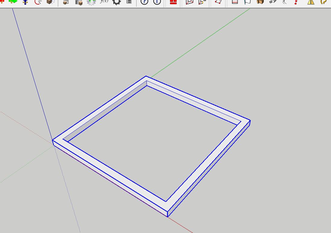
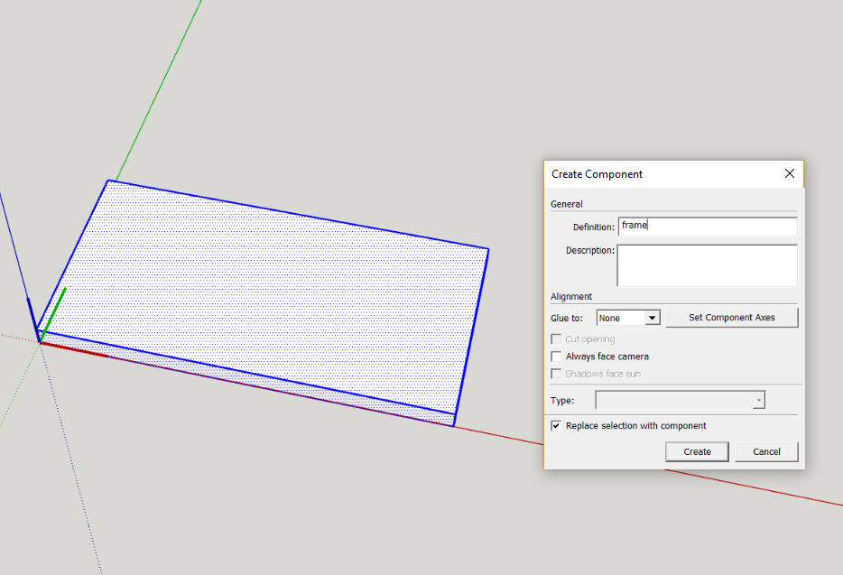
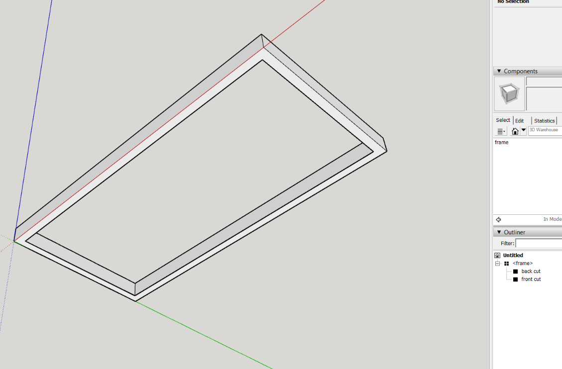
first work with a know volume, draw a rectangle 2000mm x 1000mm and pushpull a thickness of 100mm make it a component call it frame,
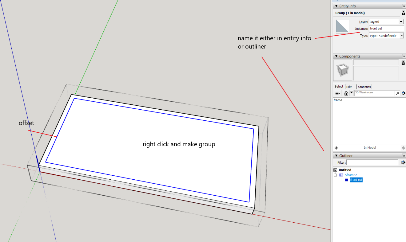
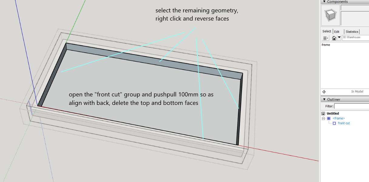
open the component and offset a face 50mm for a known frame thickness, make this a group, name it "front cut", open this group and pushpull it 100mm. Then delete the front and back faces, (reverse the rim faces) close this group.
then whilst still within the open component, "frame" draw (trace) a matching rectangle on the back surface, select this and make it a group called "back cut", open this and delete its face.
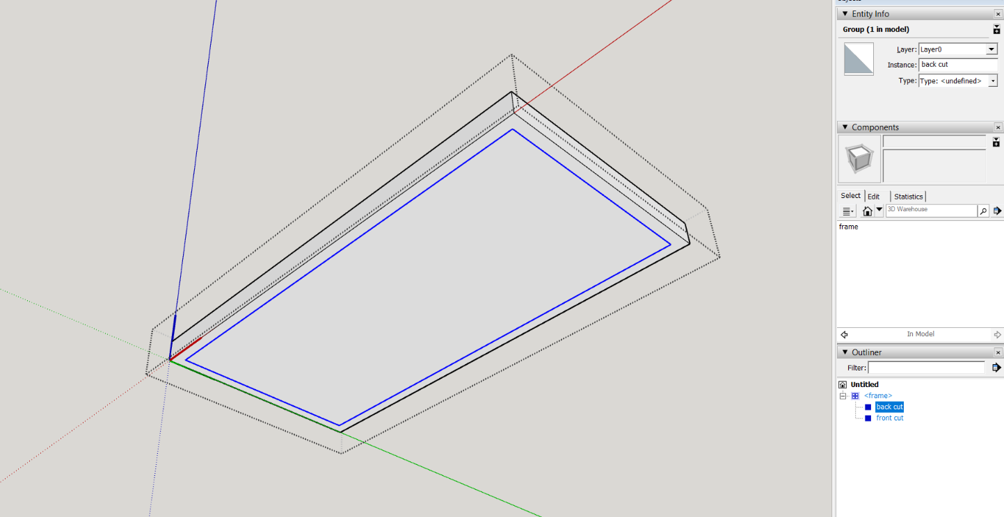
You should now have a frame that is 50mm wide and 100mm deep with and overall size of 2m x 1m
open the attribute dialog and open the position and size attribute groups of the frame component and its two embedded groups front cut and back cut
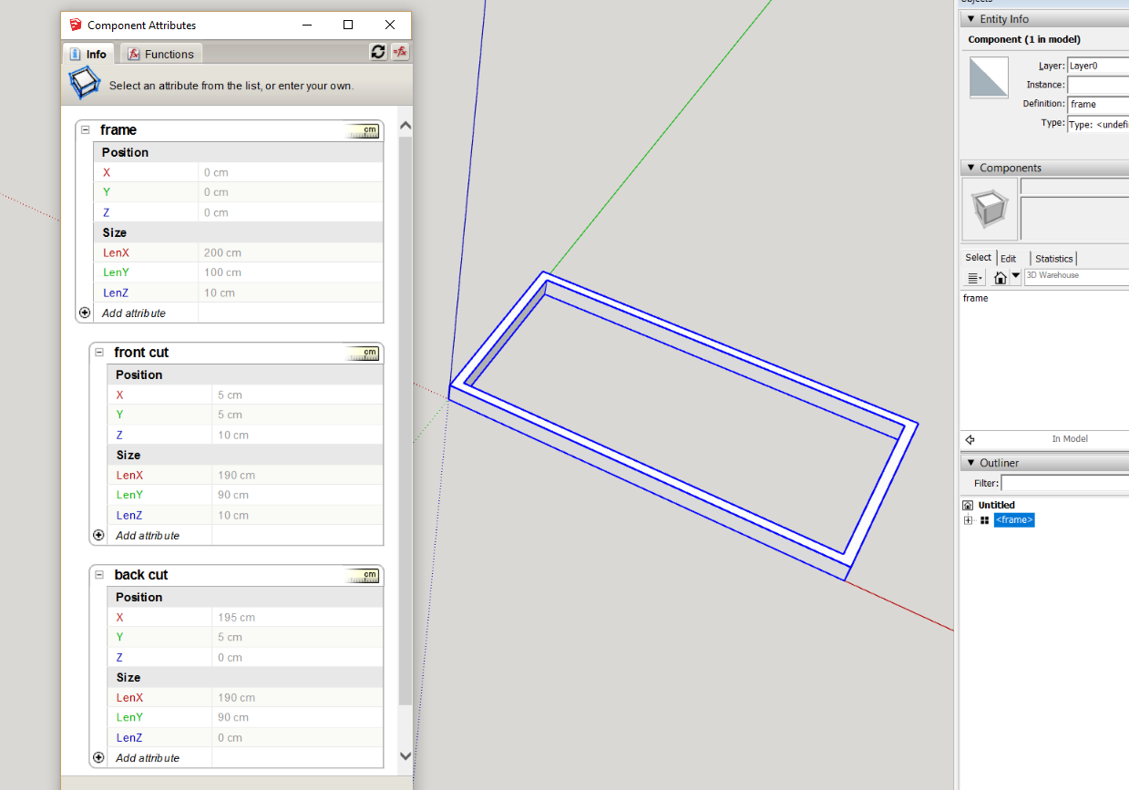
the greyed out values should be familiar with the known dimensions of the object created, the next stage is to create formula in regards to the relationship of the geometry, its important that the results match these grey values, otherwise you will create scaling issues that will come back to haunt you later.
open the option dialog.
create an attribute in the frame for the thickness, if you using metric, its important to select centimeters
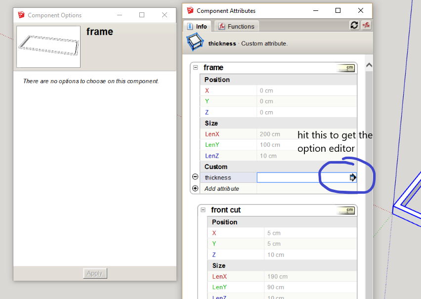
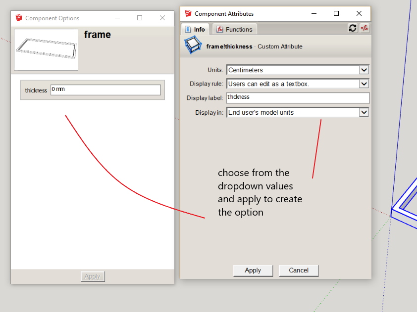
set this to 50mm (5cm)
you will note that X,Y in the "front cut" group is 5cm, this the same as the thickness (you will start to see the reason to start with known and unique dimensions for your base geometry), you can click these values in after an equals sign, by selecting the cell as one does in excel or any other spread sheet program
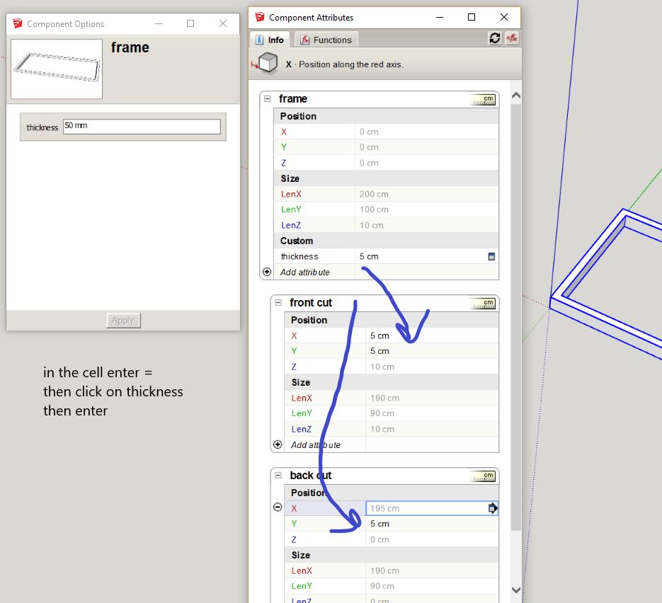
in the "back cut', Y matches, but X is 195, that is because its axis is in the other direction, for this case we will leave it alone, although you can change it if you want. So its value is the outside lenX of the frame minus the thickness
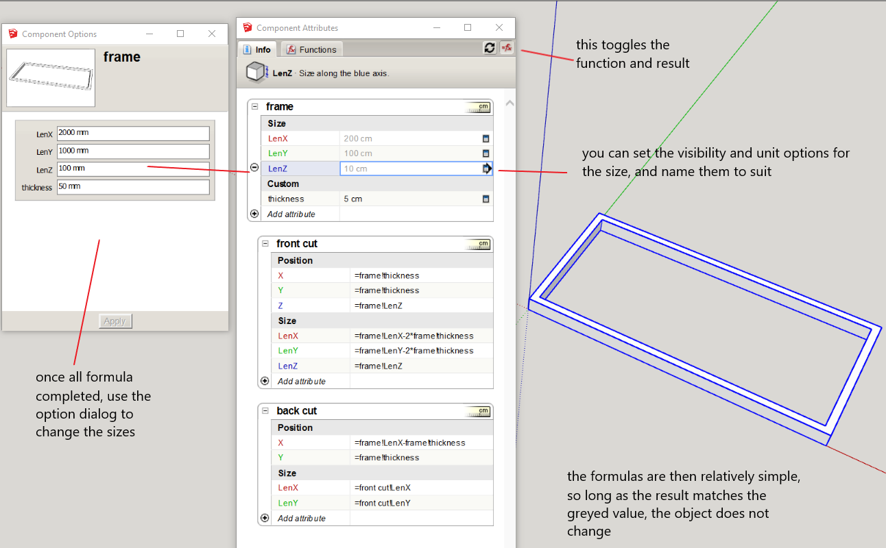
so one works out the rest
-
method 2
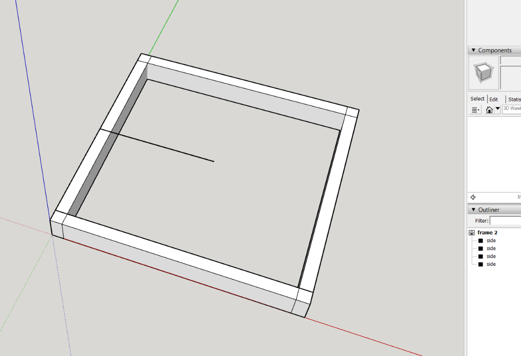
create one side of the frame, that is the thickness, depth and the length
that is 1000 x 50 rectangle pushpull 100mm to match side of the first example
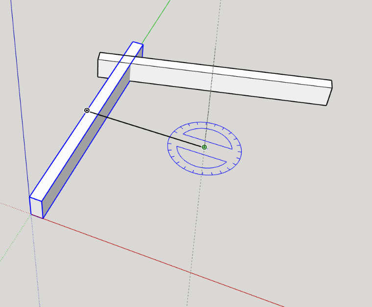
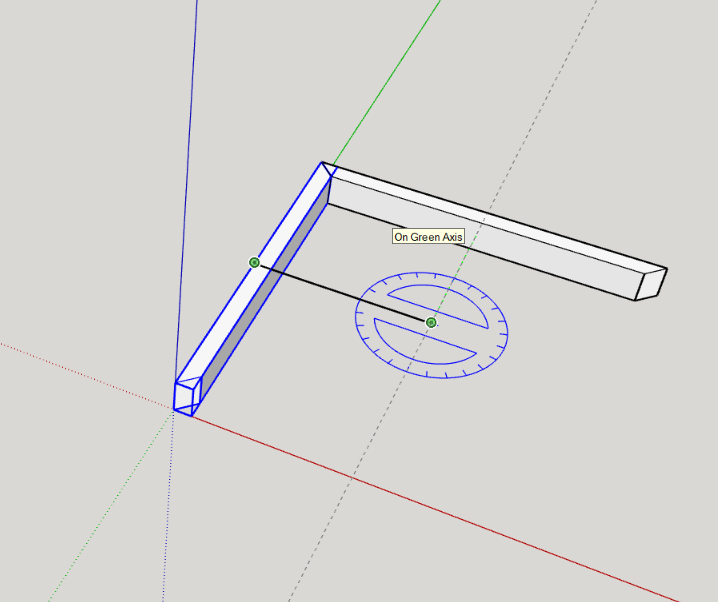
make this a group, named "side"now draw a reference line from the center of the group, 500mm long (half of its length) then select the "side" group and use the rotate tool centered on the end of this line, press control, and copy rotate it 90degs then enter *3 to copy rotate to form the full frame
this creates groups on the boundary of the component bounding box, with their axis pointing inwards
Now delete the line, select all the sides and make them a component "frame2"
open the attribute dialog and add an attribute "thick" and expose this to the option dialog, enter 50mm (5cm) as value
expose the size attributes of the frame and label them as you like
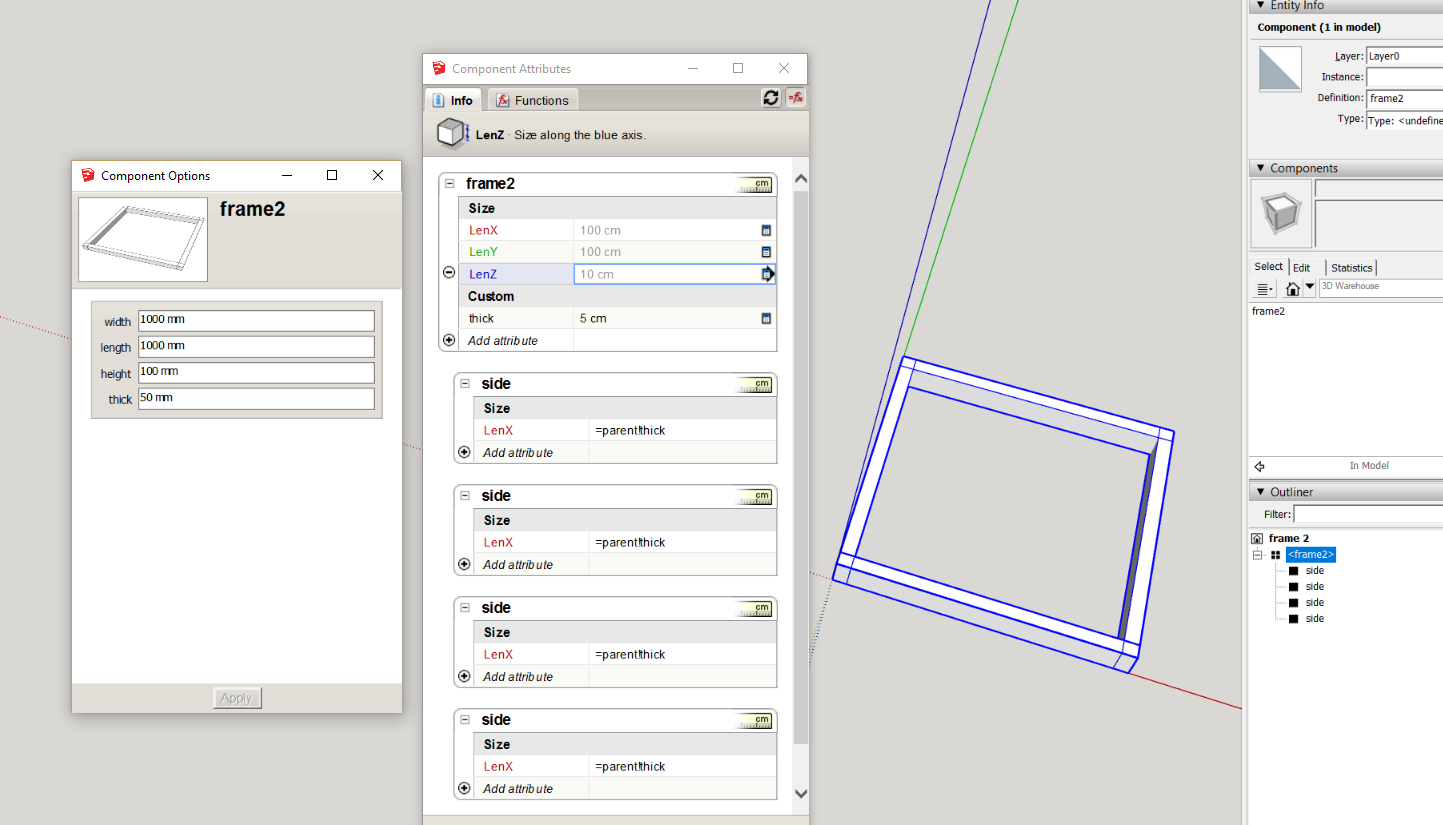
in the LenX attribute of the "side" groups write then copy
=parent!thick
(note: parent is a general term for the parent group or component and can be used instead of the name, this is good for copies and common formula)This component will now change as per options or scaling, to remove the lap of the groups, after a change one uses outershell on the groups
So open the frame2 component, select the groups and make them a component "outershell and explode me", create an attribute "thick" and write or copy
=parent!thick
(initially you will see the red # in the side groups, but this will go once the above formula is entered in thick)
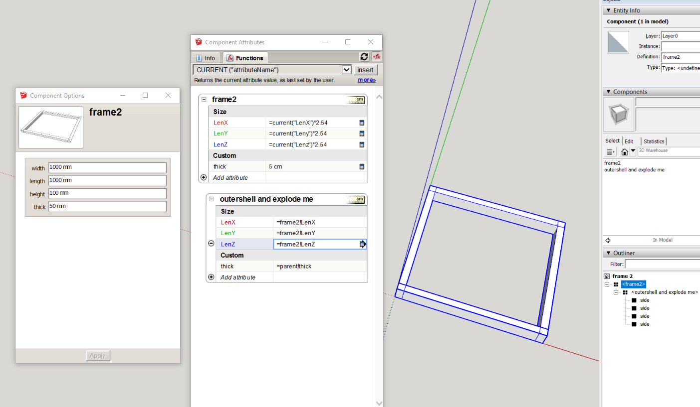
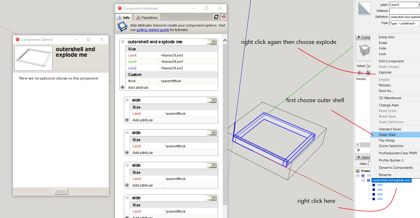
you will now have a point to use the right click menu within the outliner to simplify the DC (dynamic component).
However this destroys the dynamic part. There is a way a DC can be reinstated via a swap with a saved file of the DC. To enable the DC to match the existing attributes we need to add "current" formulas, the current function returns the last set value in inches, so for metric one converts this to centimeters by multiplying by 2.54=current("LenX")*2.54
=current("Leny")*2.54
=current("Lenz")*2.54
for the size attributes
then in the outershell component make the size attributes equal to the frame2 component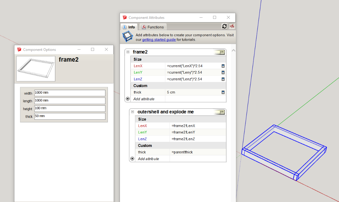
Now this DC must be saved (via right click menu) as a component file (folder of your choice) as changing the values via the option dialog will overwrite the current formula, this does not mater as the swapping DC to replace the simplified version still has.have attached the working file, the DC should be right saved before changing the options for the swapping DC
-
Method 3
somewhat follows the line of reasoning of method 2create rectangle 900x50 and pushpull it 100mm, make it a group "middle"
create 45deg wedges either end, groups "bottom mitre", "top mitre"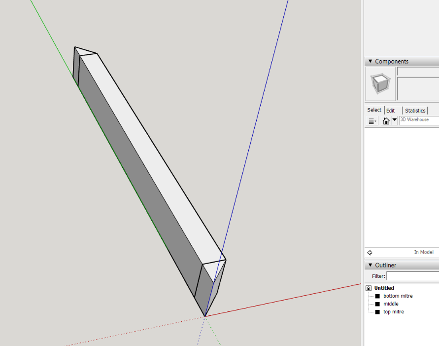
make it a group called "side" and create the relationship / formulas, again I used parent as I intend to copy and make unique sides
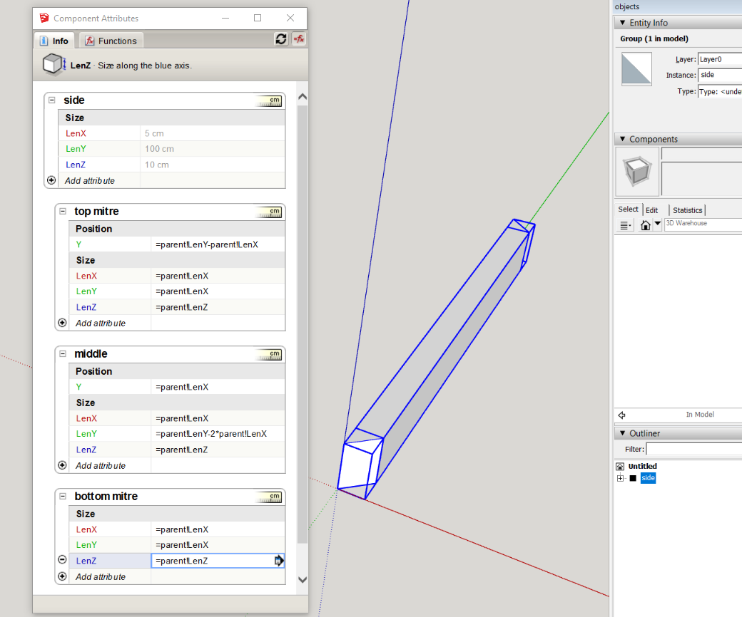
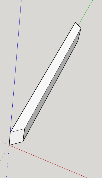
now hide the joining geometry and group, this then in formation should be similar to the side in method 2, but mitered rather than over lap
do the rotate @ 500mm as before, copy(control) *3
change the group instance name in both model info and the attribute dialog
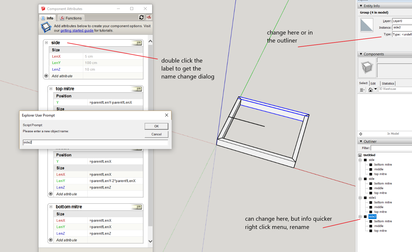
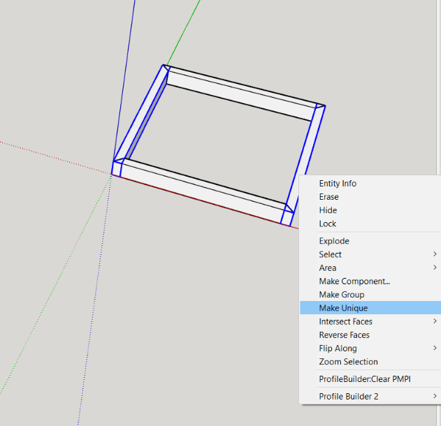
it is important to confirm that the groups are unique (changing the instance name or position may not create separate definitions (the copies initially share the same definition, that relationship needs to be broken) so pair each one and right click make unique
now make all the unique sides a component, "frame3"
fill in the relational formulas
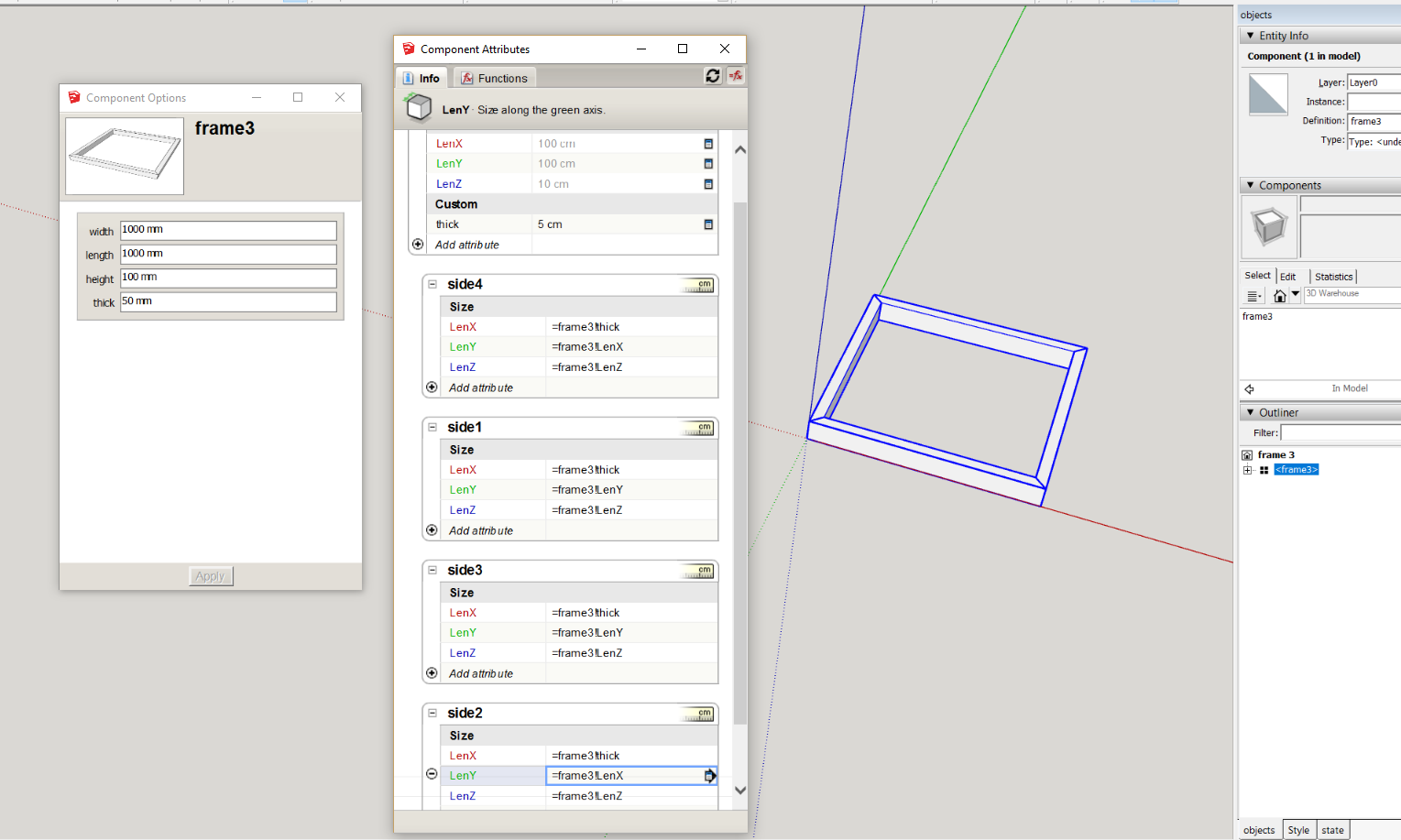
completed example attached
Hello! It looks like you're interested in this conversation, but you don't have an account yet.
Getting fed up of having to scroll through the same posts each visit? When you register for an account, you'll always come back to exactly where you were before, and choose to be notified of new replies (either via email, or push notification). You'll also be able to save bookmarks and upvote posts to show your appreciation to other community members.
With your input, this post could be even better 💗
Register Login


Advertisement