Foundation Plugin
-
Version 1.3.4 - 08.01.2019
- Added the Stemwall Foundation toolbar and icons.
- Enabled the "Draw Polyline Stemwall" tool.
- Enabled footing offsets and mitering within the draw polyline stemwall tool/menu.
Note that the ability to edit polyline stemwalls is not yet active. I am putting this out a bit earlier than I normally would so that users can give me additional feedback on the functionality and features.
Also note that to terminate your point selection process you depress the "Down Arrow" and not the Enter or Return key. I would like to change this to the Enter key but I'm not quite there yet.
The polyline tool will only draw the concrete currently, all other additional options like rebar, anchor bolts, insulation, vents and joist pockets are currently not available.
-
Many of you may have noticed the absence of regular updates the last couple of weeks. My youngest daughter (Nathanya) had to undergo an operation on both of her legs (femur) at Primary Children's Hospital in Salt Lake City, Utah about a week ago.
I have taken a small break from the coding to be with her and my wife during this ordeal and during the recovery. Unfortunately, her recovery has been slower than I had hoped for so I have spent extra time in Utah providing support. I am hopeful that her condition will continue to improve and I can jump back into the saddle in the next few days and wrap up the work on the stemwall module.

-
All the best to you and your family, Nathaniel! We enjoy your posts and work here, but it is minor, compared to your role as a father.
-
Back in the saddle.
Looks like the rebar is now working for the polyline stemwall. Lots of possible configurations so I've got to try and break it for a few more minutes to be sure it is 100% stable:
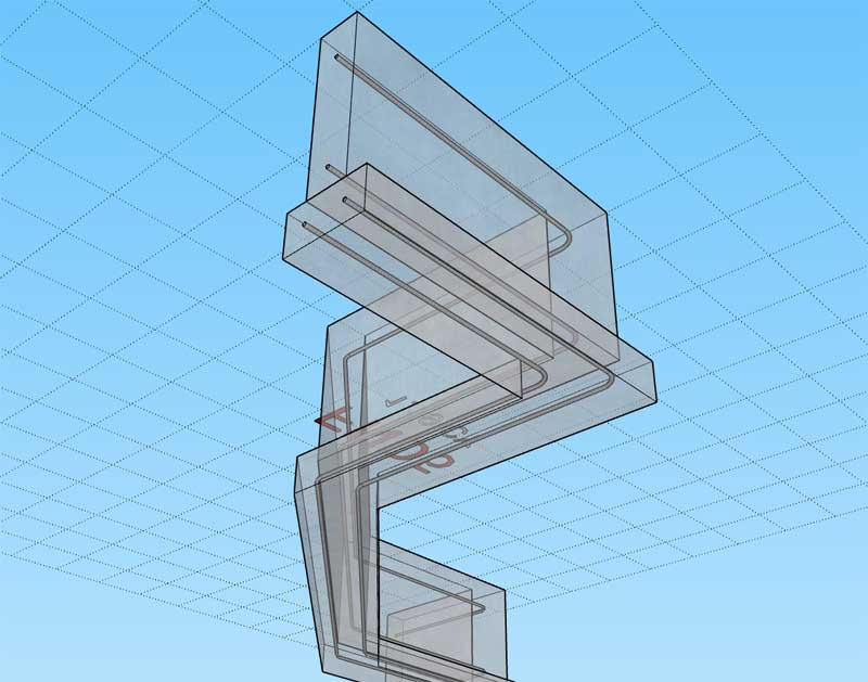
Anchor bolts are next.
-
Anchor bolts with rebar:
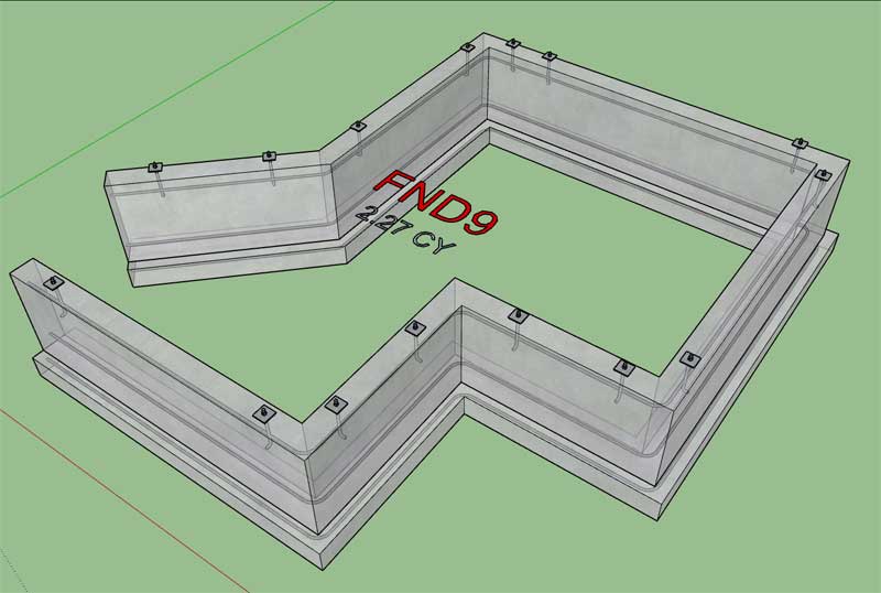
After an almost three week sabbatical it took me all of yesterday to just get back into the full swing of things and figure out where I left off. It's good to be back laying down some serious code.
Developing these plugins has got to be the most satisfying job/business I've ever had. Thank-you SketchUp for making all of this possible and more importantly thank-you to my many supporters and customers who continue to support my efforts, I will do my very best not to disappoint.
-
Frost protection for a polyline stemwall:
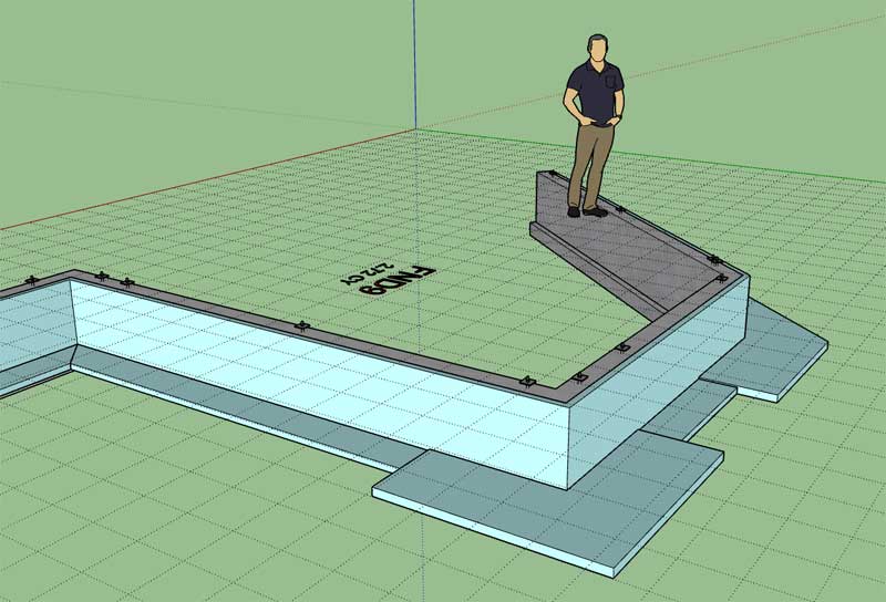
Note that the polyline tool allows the user to create not only polyline segments of stemwall foundations but also closed loops and single linear sections. Making sure the code behind the scenes is flexible enough to handle all of this is a bit of a task but I think the end result will be very functional and efficient.
-
Foundation vents are now working for the polyline stemwall tool:
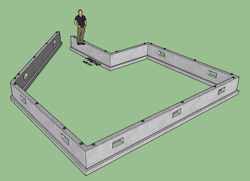
The next item of business is to create the edit menu and then check that all of the parametrics are working as advertised. Once the edit functions are up and running I will release the next version and then begin working on the "Step" tool.
I've also been giving the interior bearing tool some thought and I think I will start with only two basic types (stud wall and posts & beams). There are also quite a number of other variations that are commonly used such as steel posts etc... but I will wait until those are requested directly by the designers before diving into those.
I've also been giving brick ledges (and stemwalls) some thought and trying to come up with the most logical way of handling this type of construction. Typically when a brick ledge is called out the stemwall is thickened however the rest of the segments within a foundation may not have brick ledges and will be a different thickness. So brick ledges needs to be on a per wall segment basis.
Another item of interest is including more rebar when the stemwall is actually a full basement wall and also including vertical bars. How deep does the rabbit hole go? When it comes to full basements I will also need some tools for cutting windows and door as well as placing window and door hardware similar to the wall plugin. Additionally if the user does cut an opening in the foundation wall the rebar must be adjusted to account for this opening.
I've also had a number of requests for CMU stemwalls rather than concrete. In my opinion modeling of a CMU wall is no different than what I already have I just need to incorporate some fancy material application logic to make the solid look like CMU (similar to what I have done with the wall plugin). I will enable a CMU option that will allow the user to create CMU stemwalls.
-
The basic edit function is up and running:
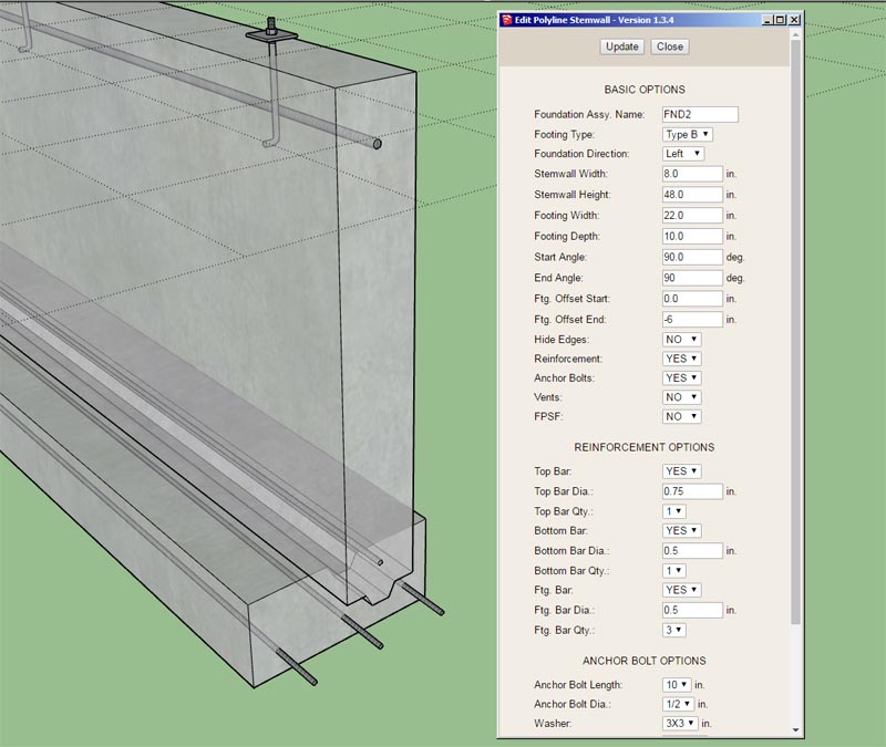
I'm quite pleased with the performance of the edit tool, it is very fast.
The last piece of the parametrics is the ability to edit the polyline that actually defines the foundation outline. About a month ago I began to explore this problem and the necessary algorithm that will be required to do this:

Inputting a Polyline (extracting its vertices)
I’m currently working on a whole new module for the foundation plugin and I am trying to implement a polyline stemwall rather than a polygon or rectangular stemwall (outline) which requires a closed loop. The initial dr…

SketchUp Community (forums.sketchup.com)
I haven't arrived at a solution yet but I will begin to tackle this problem next.
-
Version 1.3.5 - 08.24.2019
- Enabled rebar, anchor bolts, insulation and vents for the "Draw Polyline Stemwall" tool.
- Enabled the "Edit Stemwall Assembly" function/menu for polyline stemwall foundations.
- Enabled the "Edit Stemwall Outline" function for polyline stemwall foundations.
- Added a "Hide Edges" option in the draw and edit menus for polyline stemwall foundations.
Note that the hide edges option only hides the edges of the concrete at the terminal ends of the stemwall and footing. This feature will come in useful where the user is utilizing the upcoming stemwall step tool to adjoin sections of foundation together.
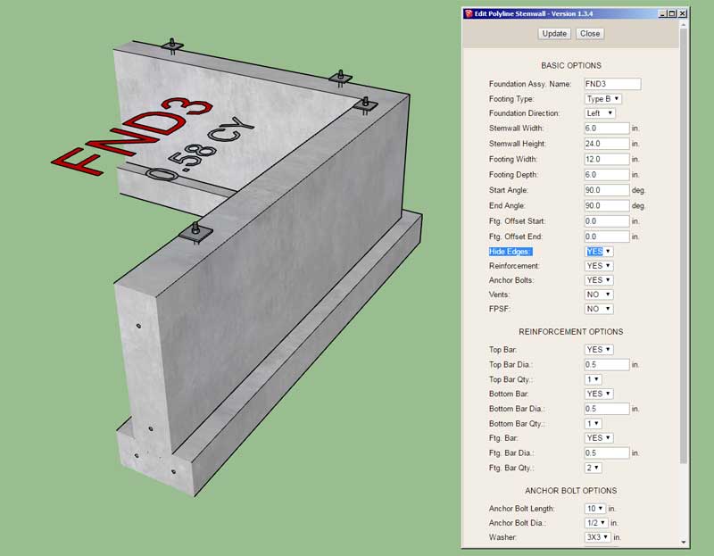
Checking end conditions with FPSF option enabled:
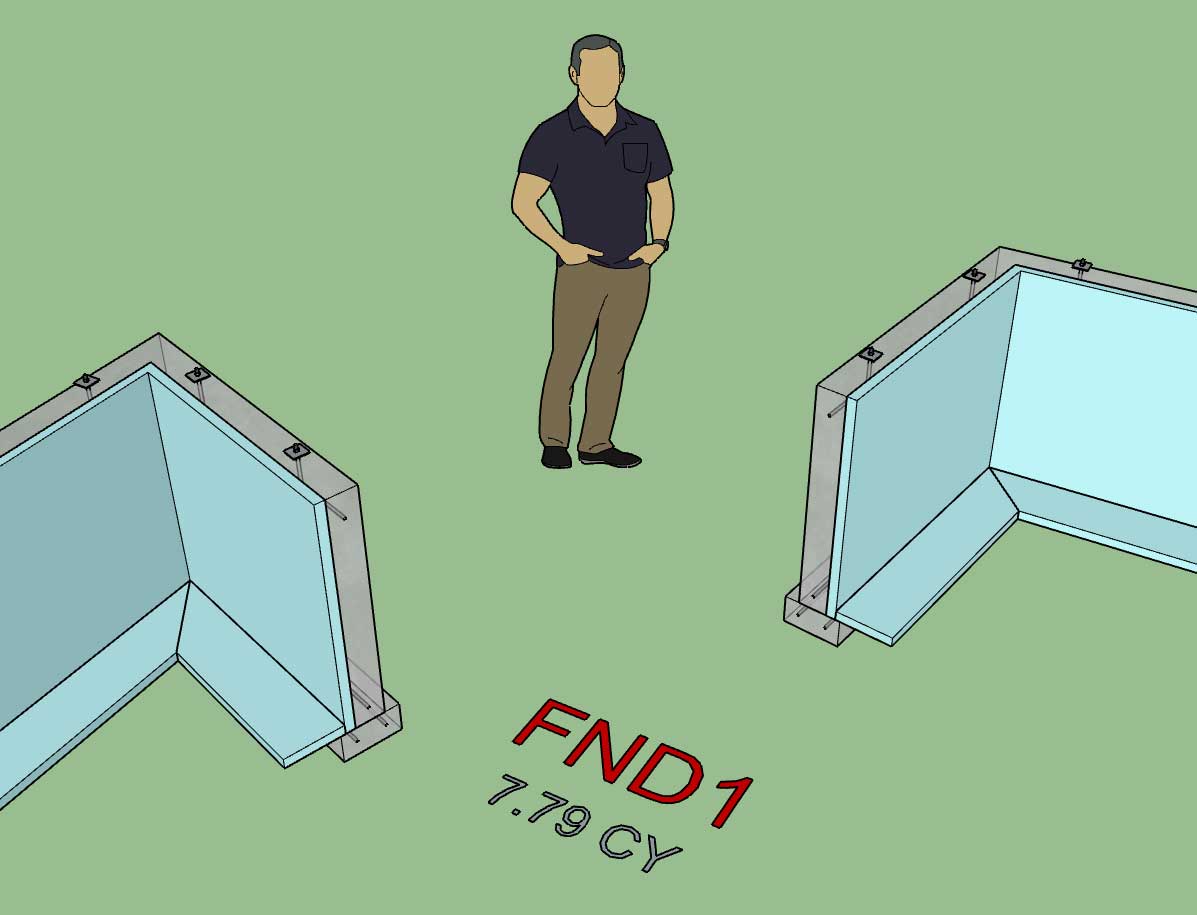
The next item to be addressed is the stemwall step tool that will work in tandem with the stemwall polyline tool just completed. Being that this is a completely new feature there may be further refinements necessary or features that further improve the functionality. Please send me any feedback via the forums or email.
-
After looking at various details (including some of my own) I am wondering if enabling an option to include a 4" DIA drain pipe along the footing might be of some interest. Please let me know know your thoughts on this. I haven't had too much call for it but I have often called one out in many of my own plans and drawings:
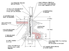
http://design.medeek.com/cad/autocad/STEMWALL_DETAIL.pdf
Parameters would probably be:
1.) Diameter: 4"
2.) Bend Radius: 4"
3.) Wall Thickness: 0.125"
4.) Hollow: Yes/No
5.) Ftg. Clearance: 2"Additional layer for PVC and a PVC material (RGB: 149, 219, 184)
-
yes please
-
The drain line would be good. We also use slab sub-drains.
-
Version 1.3.6 - 08.25.2019
- Added a drain pipe option in the draw and edit menus for polyline stemwall foundations.
- Added a drain layer in the Global Settings under the "Layers" tab.
- Fixed a bug with the hide edges option with regards to closed loop polyline stemwall foundations.
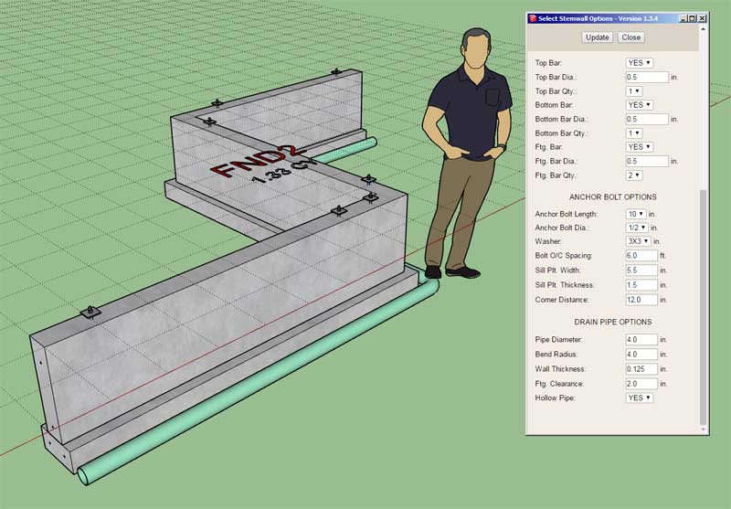
** NOTE **
If you have previously installed the plugin and are upgrading to this latest version in order to utilize the new drain pipe feature please do the following action once you have installed Version 1.3.6:
1.) Click on the global settings tab.
2.) Click on the Layers tab within the Global Settings.This action will initialize the "Drain Layer" for future use. New installations of the plugin will automatically initialize the new layer when they enable the layers options for the first time.
In order to help minimize the model size I've limited the drain pipe circle profile to 16 segments rather than the usual 24 segments. Visually this seems to be the best compromise.
I've also added the option to draw the drain pipe as a simple solid or hollow as shown with the "Hollow Pipe" option. By default this is set to "YES".
The drain pipe is positioned with its bottom level with the bottom of the footing. Currently there is no vertical offset, but I'm not opposed to adding one if there is call for it.
The other parameters are fairly self explanatory.
-
With regards to estimating it wouldn’t be that hard for me to calculate the lineal feet of drain pipe as well as give a count on the number of elbows (45, 90 etc…) I’ve added this to the todo list.
-
Do you need to model the wall thickness of the pipes? With all the bends that you also model, it might add a lot of geometry to a larger house plan.
-
@pbacot said:
Do you need to model the wall thickness of the pipes? With all the bends that you also model, it might add a lot of geometry to a larger house plan.
That is the point of "Hollow Pipe" option, if you don't need to model the actual inside of the pipe you can toggle it off and just represent the pipe as a solid object.
It does add a lot of unnecessary geometry in my opinion but some users might want it modeled exactly.
-
Version 1.3.7 - 08.26.2019
- Added a drain pipe option in the draw and edit menus for rectangular and polygon slab-on-grade foundations.
- Increased the speed/performance of the drain pipe modeling method.
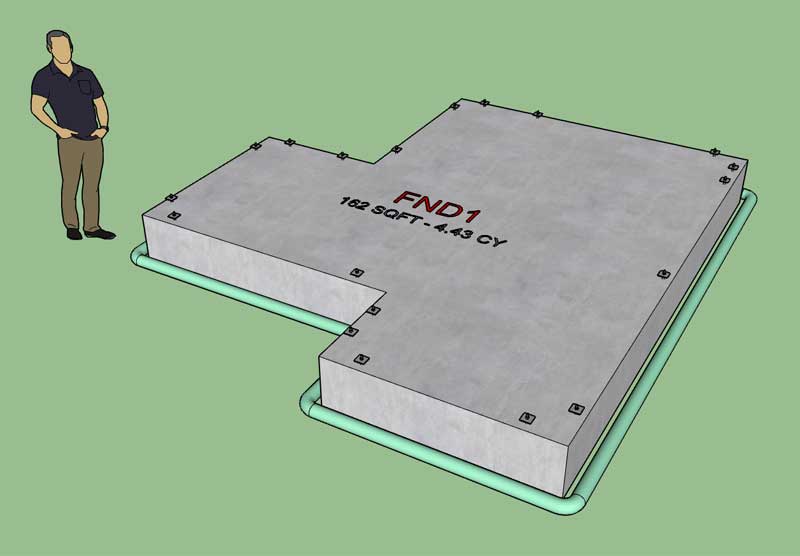
The smoothing routine I was using was a major slowdown/bottleneck so I have removed it for now. I will need to experiment with an improved smoothing routine but for now it is not imperative, the pipe is a proper solid and group.
As you can see in the model there are some visible edges at each elbow, these can be removed by adjusting the smooth normals/soften coplanar options within the Soften Edges tool in the SketchUp Default Tray.
-
Working on the step tool this evening. This one gets real interesting, lots of possible configurations even though it is a simple linear piece of foundation (ie. Top Step, Bottom Step, Double Step).
I haven't spent too much time looking at the rebar yet for a step but I'm starting to now and just wondering how everyone would like it drawn/configured. I can terminate the rebar lengths at the step or I can extrude them along to follow the path of the step(s). Any thoughts, cad drawings or details showing preferred rebar layout would be extremely helpful.
I have enough tricks in coding toolbox now that I can pretty much make the rebar do anything you want, I just want to make it as realistic as possible without getting overly complicated.
Along that same vein I think I have the other advanced options figured out for a stemwall step: Anchor Bolts, Vents, Insulation. However, I don't know what I want to do with the drain pipe just yet. Obviously it needs to transition from one height to another but what is the preferred way to model this?
-
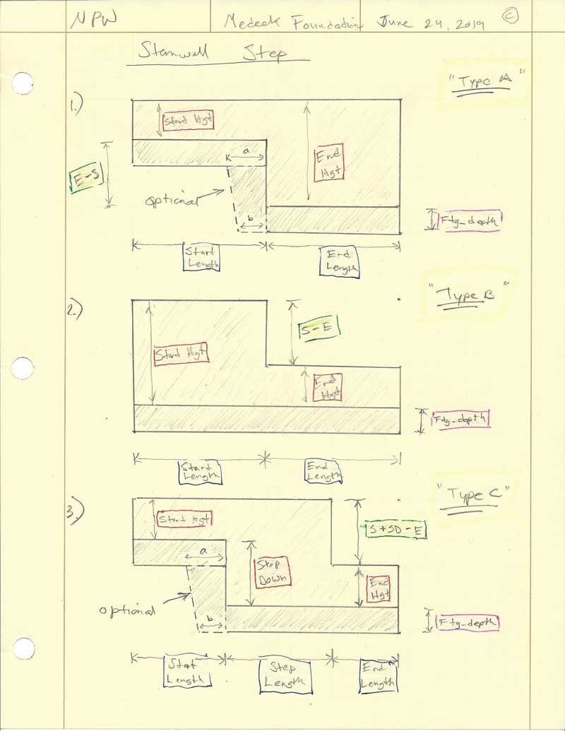
After some serious head scratching and tossing around various parameters I've managed to boil it down to this:
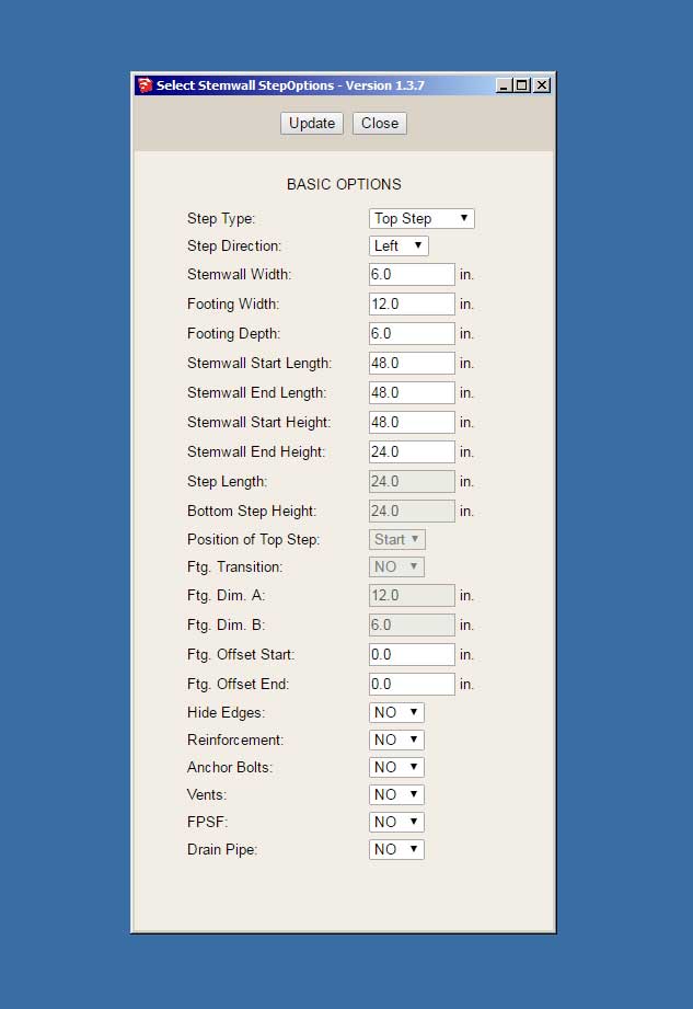
Three different step configurations: Top, Bottom, Double (see previous drawing for details)
The Double Step has three additional parameters as well as the option for the Ftg. transition.
As you can see it gets rather complicated, or at least appears so. In actuality it is fairly simple once you understand what each parameter does.
-
First look at the wireframe preview for a stemwall step:
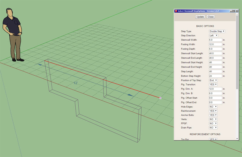
Tomorrow I start in earnest to code the concrete portion of the module now that all of the supporting infrastructure is in place. Then from there it is rebar, anchor bolts etc...
Hopefully this module combined with the polyline stemwall module will give designers the flexibility they need in order to model any type of stemwall or basement foundation.
Advertisement


