3D Truss Models
-
I've been pondering how to control the truss layout of these complex roofs and after much thought and sleeping on the problem for a night I've come to the conclusion that for all but the simplest roof types (gable or half hip both ends on a rectangular footprint) there needs to be user specified girder trusses.
Even the simplest hip roof (rectangular, hip both ends) needs two girder trusses. The algorithm should be smart enough to detect the layout in such a simple case but even so the setback of those girder trusses will have to be user controlled. With my existing hip set tools this is provided as a simple numeric value since the location and orientation of the hip girders is already determined.
When you move to complex roofs the location of the girders becomes completely open ended. In other words we have too many degrees of freedom to confidently compute the solution. You can't solve a multi-variable math problem if you have more variables than you have constraints or equations. That is the nature of this beast.
My thinking is this:
1.) The user creates the perimeter or outline of the complex truss roof just as one currently does with the complex rafter module. The general roof shape and secondary features are generated (ie. sub-fascia, sheathing, cladding, gutter, soffit and fascia etc...), however the actual truss framing is not generated with this initial creation step.
2.) Next, the user clicks the girder truss creation tool which allows one to add in specific girder trusses between any two points within the roof outline (layer). The algorithm will require that the two endpoints of the new girder either terminate on the perimeter or along the length of an existing girder. Obviously the new girder cannot have both of its points on a perimeter edge or another girder, so that check will be built in. An HTML dialog box will allow the user to set a number of properties of the girder (ie. 2-ply, top chord depth, bottom chord depth, truss configuration, panel number for hip girders etc...)
3.) Once the girders are set then a context menu option will allow the user to attempt to generate the actual truss framing. If the girder layout is inconsistent, or illogical it will fail and display the applicable warning to the user. I'm still feeling this one out a bit so there may be an additional step where the user determines the rotation of the trusses in each zone created by the girder trusses.
I think I can make this work but only time and some extensively testing will tell. I think the concept is fundamentally sound but as I've learned in the past with other programming problems, the devil is in the details
-
Here is an excellent example of a complex roof that involves multiple girders and overframing using valley sets:
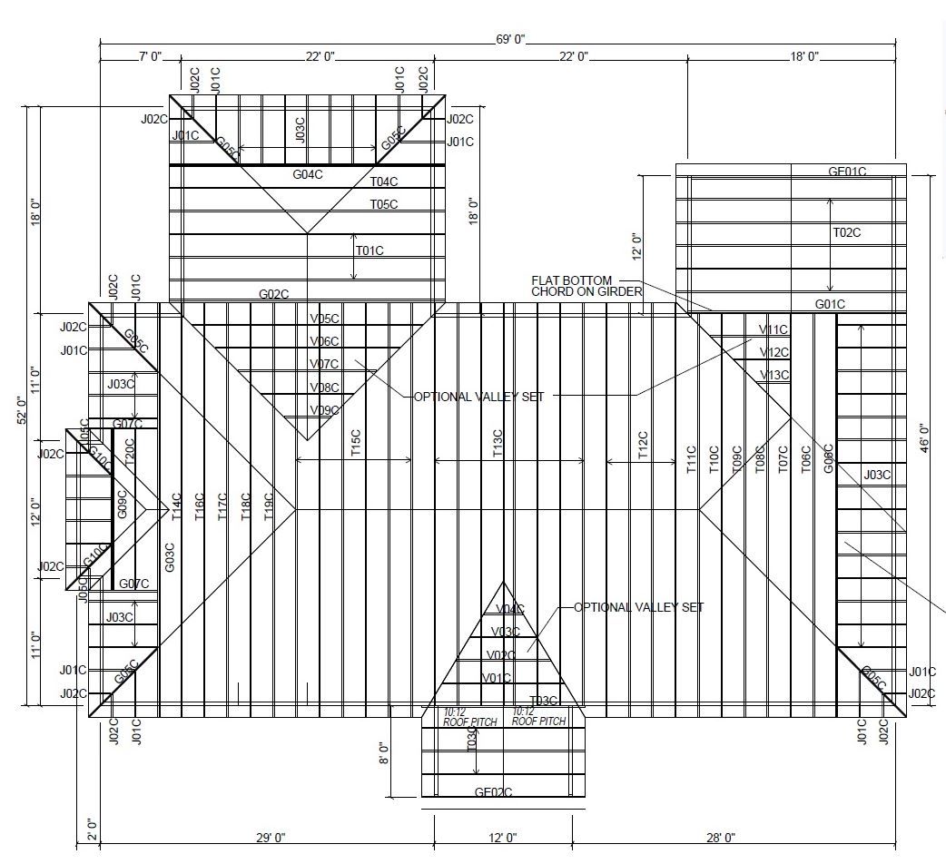
What I find particularly interesting with this case is the use of the half valley set on the right hand side. Why is this? This is cause for more investigation.
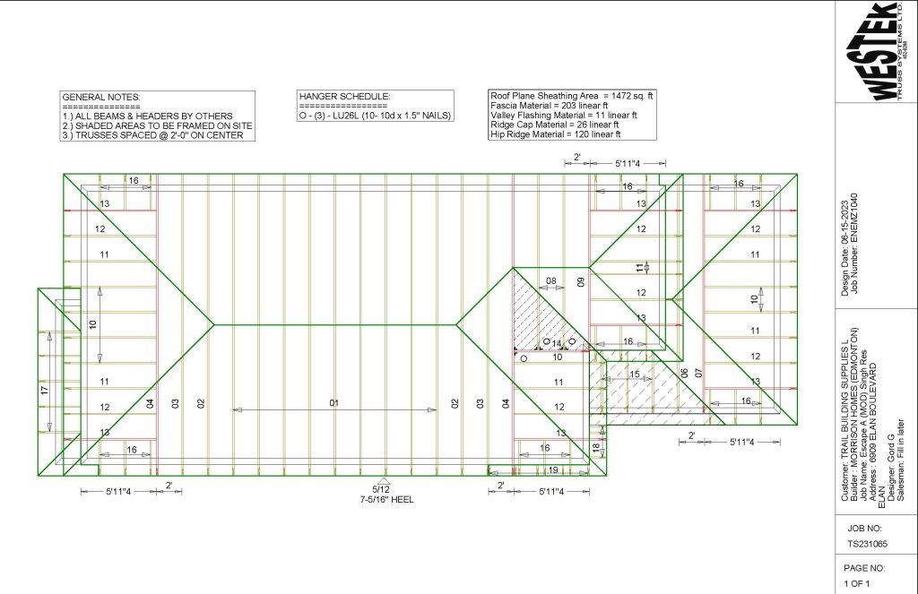
This next one is a bit confusing because it shows multiple levels of roofs, but the doubled up hip is what is most interesting, specifically trusses 08 being carried by the cross girder 14 which is then carried by girder 04. The shaded region over this section is to be framed onsite per the notes, or optionally one could valley truss this out with a half valley set, I’m starting to see a pattern here and I think I know why.
-
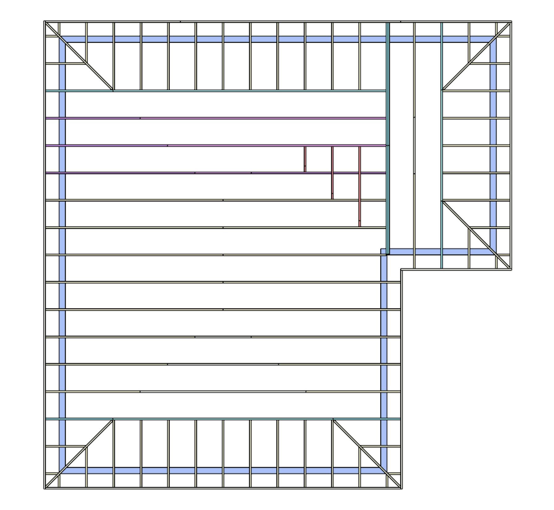
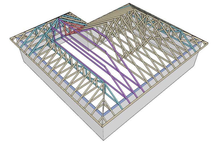
The proper way to truss out the previous L-shaped roof would be the use of a “half valley”. I’ve never actually seen one of these framed up in real life but based on the layout drawings I’ve seen I know they exist. If some one has some additional shop drawing, images or even truss layouts of these (shaded red in the model below) please send me some examples.
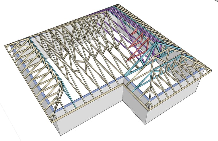
-
Personally, I will normally just call for stick-frame fill framing in these areas in lieu of the multiple 'half-valley' trusses. I'm not sure if either way is more efficient for the framers.
-
Here is a simple schematic of a slightly more convoluted roof to try and understand the methodology a bit better:
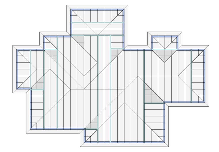
The two girders in the center of the structure could probably be combined into one larger girder, but maybe it is better to distribute the loads across to trusses instead of one. The shaded areas are the valley sets or overframing required to fill in the voids.
This design requires 10 main girders and 5 cross girders. Notice how there is a hip truss at each outside corner and a half valley set at each inside corner. When to inside corners are symmetric we end up with a full valley set.
Based on these patterns that are emerging I might be able to auto place the girders or at least provide an initial placement which then can be further refined by the user.
-
Each girder will break up the roof outline into zones. Then using a combo of boolean subtraction and intersection we should be able to generate this as a starting point:
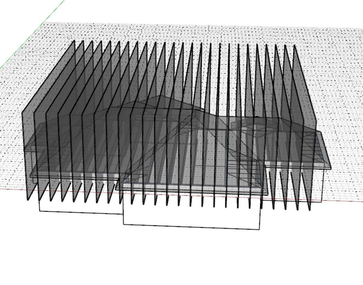
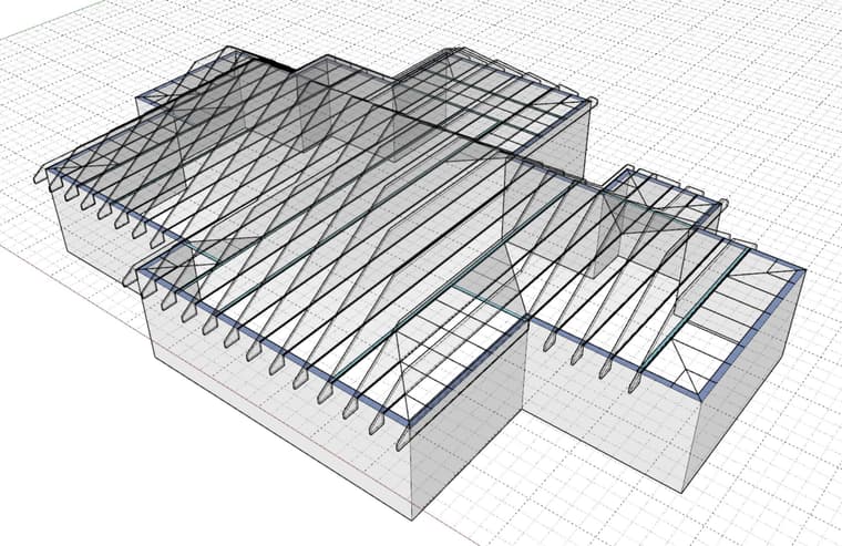
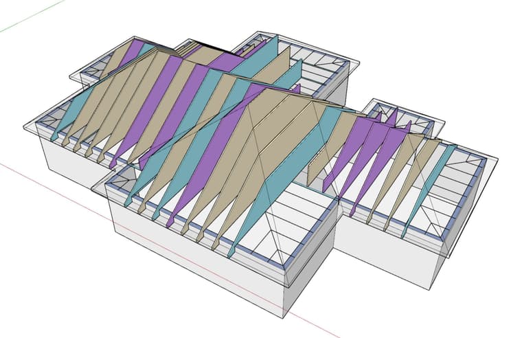
The blue shaded truss outlines are the girders, the purple shaded are the trusses requiring a further subtraction step to make the correction for the valley truss sets, notice the third purple truss from the right.
Basically I'm walking you through my algorithm for generating the truss geometry data so I can then draw each truss. As you can see this is not a trivial process. Lots of steps and lots of "edge cases" that can potentially trip it up. That is what I mean when I say the devil is in the details. However if the basic algorithm is sound one should be able to add in logic to deal with the issues and in the end you end up with a robust piece of code. These are the kinds of things that keep me up at night.
Based on these slices we should be able to extract the key geometric points that define each truss and then send that data to the separate truss "draw" algorithm which sorts out all the messy details on how to place the webs, plates and all that fun stuff.
-
Version 3.8.1 - 05.13.2026
- Enabled a second layer of wall sheathing for common and scissor trusses.
- Enabled XPS (blue, green, pink and grey), ISO, EPS, GPS, and PU foam insulation within the wall sheathing and wall sheathing 2 options.
-
Version 3.8.2 - 05.17.2026
- Cleaned up the filed and folder structure of the complex roof module.
- Enabled the truss template in the complex roof module.
- Added a "Roof Family" parameter into the draw and edit menus of the complex roof module.
- The complex roof edit menu now displays and allows configuration of custom roof planes.
-
I’m now porting the Truss plugin over to Rhino. I’ve started a separate Rhino thread here for those that are interested:

Medeek Truss
My name is Nathaniel P. Wilkerson and I am the creator of the Medeek suite of tools within SketchUp. I’m not sure if this is the correct forum or category but I am in the process of porting my “Truss plugin” from Sketch…
McNeel Forum (discourse.mcneel.com)
-
Version 3.8.4 - 08.20.2026
- Added an advanced (weighted skeleton) solver for complex roofs.
Note that I have retained the "Legacy" solver for now. When you draw or edit a complex roof you will now have an additional parameter which will allow you to choose the solver or primitive engine. I've tested the new solver with well over 50+ roof configurations however I'm sure a few cases will sneak through.
Both solvers should yield the same result but if they do not please report that information to me via email (nathan@medeek.com).
The new solver is what is called a "weight straight skeleton". It uses wavefront propagation. It is the "proper" way to solve a complex roof. The legacy method used a system of boolean subtractions to carve out the complex roof organically from an initial prismatic solid. Overall the legacy method is pretty good however there are certain oddities or roof geometries that will foul it up, hence the need to develop the more advanced method.



Hello! It looks like you're interested in this conversation, but you don't have an account yet.
Getting fed up of having to scroll through the same posts each visit? When you register for an account, you'll always come back to exactly where you were before, and choose to be notified of new replies (either via email, or push notification). You'll also be able to save bookmarks and upvote posts to show your appreciation to other community members.
With your input, this post could be even better 💗
Register Login


Advertisement