3D Truss Models
-
That cladding extension parameter was a real pain. However, as you can see in the image below it is now working for the half hip configuration:
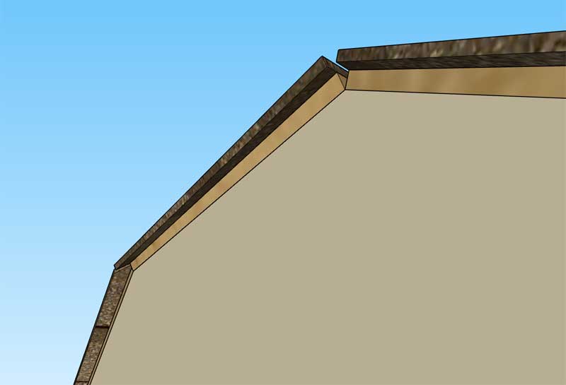
Cladding is now complete, thankfully
I'm thinking about working on the roof plane labels next and then on to the sub-fascia.
-
First look at labels with cladding and sheathing:
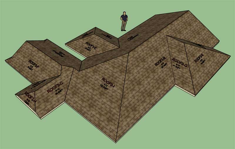
View model here:
3D Warehouse
3D Warehouse is a website of searchable, pre-made 3D models that works seamlessly with SketchUp.
(3dwarehouse.sketchup.com)
I need to add a scale factor for the text size which will allow the user to adjust the size of the text for the labels. I actually need this for the entire plugin, not just this module.
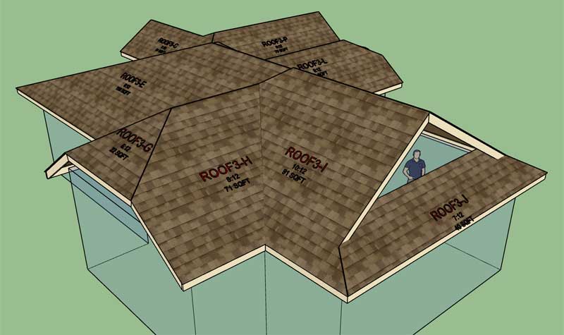
The other issue is ordering the roof planes which may or may not be the same as the number of roof edges. Note, that sometimes roof edges are collinear and if their other parameters are the same (ie. pitch, overhang etc...) the roof planes will merge into one. For example take roof plane "N" in the model shown, it is bounded by two separate eave edges.
The ordering of roof planes gets a little bit interesting in these cases but all one can do is one's best to bring as much order to the chaos as possible.
Each label is centered on its respective roof plane (via the bounds.center method), sometimes this works out and sometimes it doesn't. I don't really have any ideas on a better algorithm for the time being.
-
Starting to work on the sub-fascia module. Everything is pretty clear to me except for the half hip. I actually have never added a half hip roof type to the plugin until now. My proposed solution for a half hip with sub-fascia is:
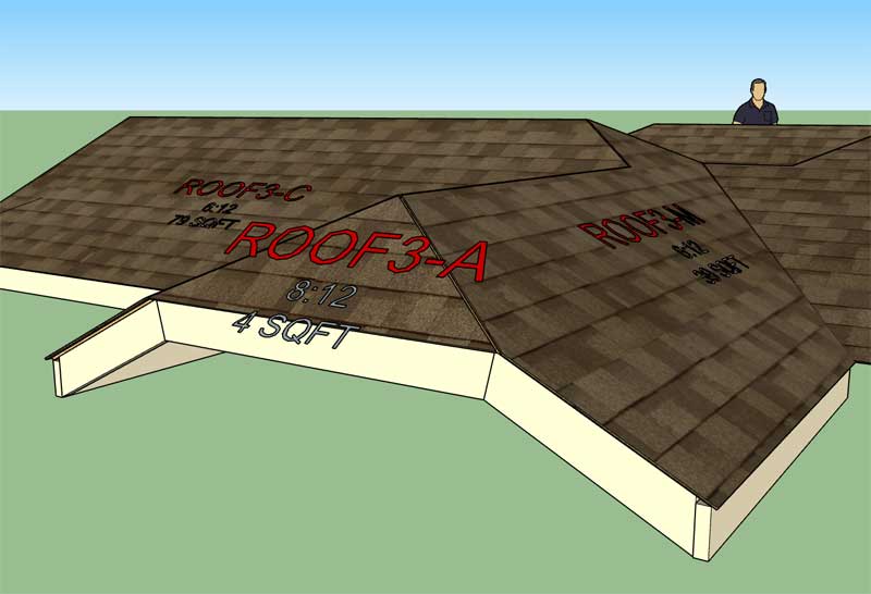
I think it makes the most sense to bevel cut the rakeboard as shown so that the bottom edges of rakeboard flush up. Please feel free to comment or suggest and alternative solution.
-
Version 2.5.4 - 10.08.2019
- Added cladding for complex roofs.
- Added labels for complex roofs.
-
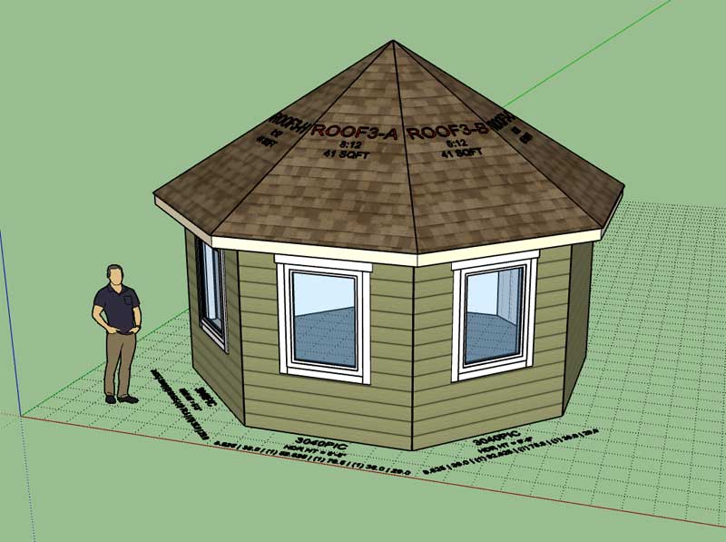
Looking at some of Larry Belk's roofs this morning got me thinking about those crazy octagon shaped turrets often employed on upper end houses. It seems they are rather popular these days, and I would imagine quite fun to frame up.
I honestly wish I was living in an area where a lot of this type of house building and framing is going on. It would be very educational to visit a few of these job sites and observe how things are going together and ask a few (many) questions.
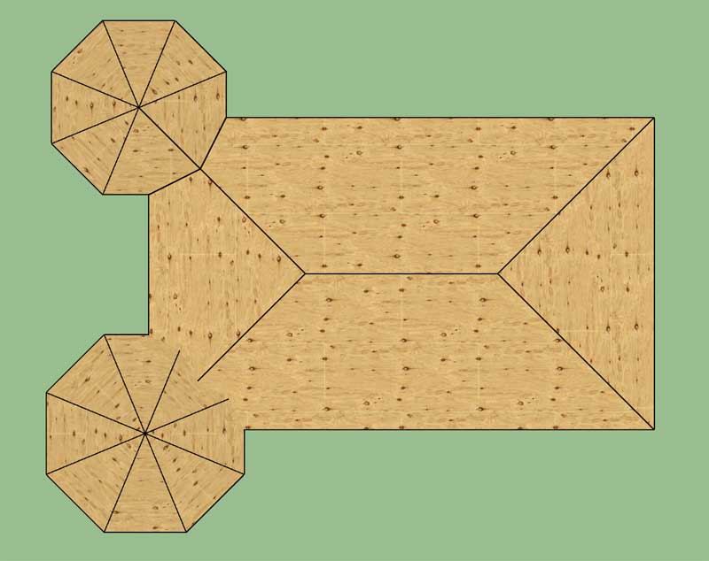
The image below shows what solution (upper octagon) the complex roof module will come up with when the octagon is integral with the rest of the roof (all one assembly):
View model here:
3D Warehouse
3D Warehouse is a website of searchable, pre-made 3D models that works seamlessly with SketchUp.
(3dwarehouse.sketchup.com)
However, the solution you will probably want is the lower octagon turret where the octagon outline is fully preserved.
When the plugin creates the roof primitive it will only at a maximum have as many roof planes as there are roof edges (eaves). The straight skeleton algorithm cannot add in additional roof planes that do not border a roof edge, this is just the way it works mathematically, there is nothing I can do about this behavior.
I will need to give this type of situation some more careful thought and consideration. I have a few ideas up my sleeve already but the implementation is always the crux of the problem.
-
One thing I haven't considered yet are roof returns (gable and half hip):
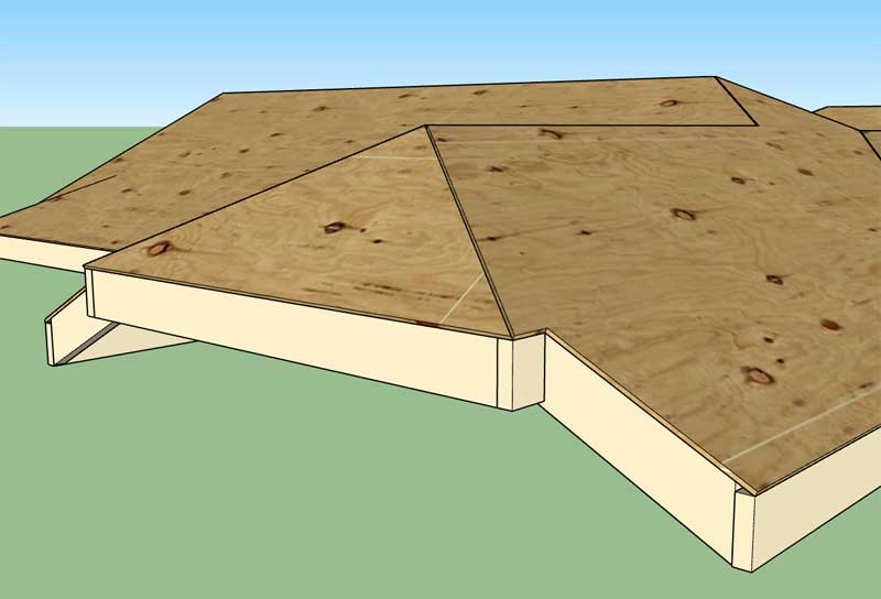
However if you are going to go to the trouble to put a return on the half hip you will probably also do a lower return at the fascia line as well:
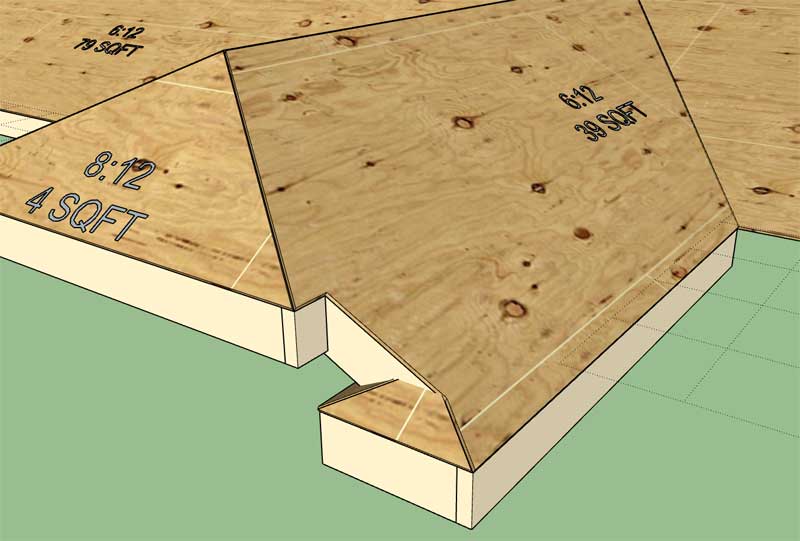
Eventually half hips will need to have an option for returns: Upper, Lower or Both
Also note that the pitch of the lower roof return equals the pitch of the half hip but this may not always be the case. Also the lower roof return may have three possible configurations: Full, Hip or Gable.
The complexity of complex roofs knows no bounds.
View model here:
3D Warehouse
3D Warehouse is a website of searchable, pre-made 3D models that works seamlessly with SketchUp.
(3dwarehouse.sketchup.com)
I don't want to get lost in the weeds right now so I'm not going to implement roof returns for gable and half hip roof ends just yet. This will have to be work for a later date. However, it was worth exploring and considering the possibilities.
-
Version 2.5.4b - 10.09.2019
- Fixed a bug with non-orthogonal roof plane labels for complex roofs.
- Resolved some minor bugs and stability issues with half hip and dutch gable roof options with complex roofs.
View model here:
3D Warehouse
3D Warehouse is a website of searchable, pre-made 3D models that works seamlessly with SketchUp.
(3dwarehouse.sketchup.com)
If you are BETA testing the complex roof module I highly advise upgrading to this latest version as it addresses a problematic stability issue I was having with dutch gable roofs.
-
Version 2.5.5 - 10.10.2019
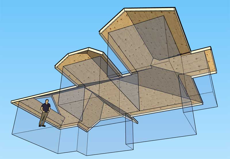
- Added sub-fascia and rakeboards for complex roofs.
View model here:
3D Warehouse
3D Warehouse is a website of searchable, pre-made 3D models that works seamlessly with SketchUp.
(3dwarehouse.sketchup.com)
I've eliminated the FLUSH option and only kept the BEVEL and DROP option for sub-fascia. I don't know that the FLUSH option ever really made any sense. If enough people complain I can always bring it back.
We have enough "real" geometry now to show the basic outline of the roof. I will next go after the soffit and fascia and then the gutters. I'm still thinking about downspouts, a method to customize their placement makes the most sense.
I may have to take a break from the code for a couple of days (not really excited about that) as I have some traveling to do.
-
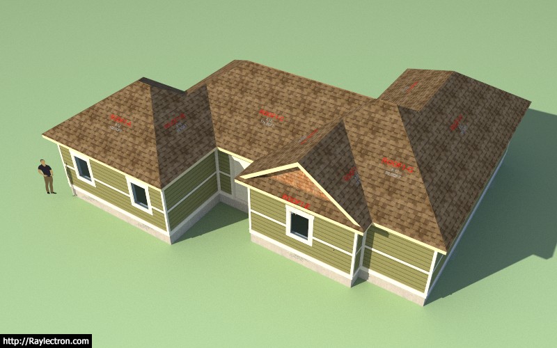
I think the complex roof will be a welcome addition once I have moved the ball a bit further. Testing the plugin suite combined with the complex roofs is quite satisfying but it does make me realize that so much more still needs to be done, not only with the roofs but also with the walls and other features (ie. porches, decks, steps etc...)
View model here:
3D Warehouse
3D Warehouse is a website of searchable, pre-made 3D models that works seamlessly with SketchUp.
(3dwarehouse.sketchup.com)
As they say the devil is in the details and there can be a lot of details with these residential (and commercial) structures.
I'm now 4 years into these plugins (the first iteration of the Truss plugin was released on 10/07/2015), well technically only 1.5 years full time. I think I've made a fairly sizable dent, but looking at what still remains to be done, I'm not sure I even see an end in sight.
I beginning to warm up to the idea that I may need some programming help (perhaps even partners). If you're familiar with the SketchUp API and interested in possibly getting involved in the development of these plugins, give me a shout I would be interested in talking with you.
-
I'm starting to see the number of new licenses per month accelerating. This tells me that the plugin(s) are becoming more widely known, and also as they further mature, they are becoming an ever more viable alternative to other similar design softwares. Now is the time to step on the gas and pick up the pace of the development even further. Nothing scares me more than providing an inferior or defective product to my customers, and I realize that the plugins are still far from the polished, comprehensive and professional tools that I would like to see them become.
-
I'm now at the stage where I am beginning to work through my algorithms for the actual framing of the roof (ie. rafters, ridges, hips and valleys). I begin by breaking down the edges of the roof so that I can determine which are hips, valleys, rakes, flying hips etc... I also want to actually label each as such so when it comes time to dump all of this into the estimating module there is some order to it.
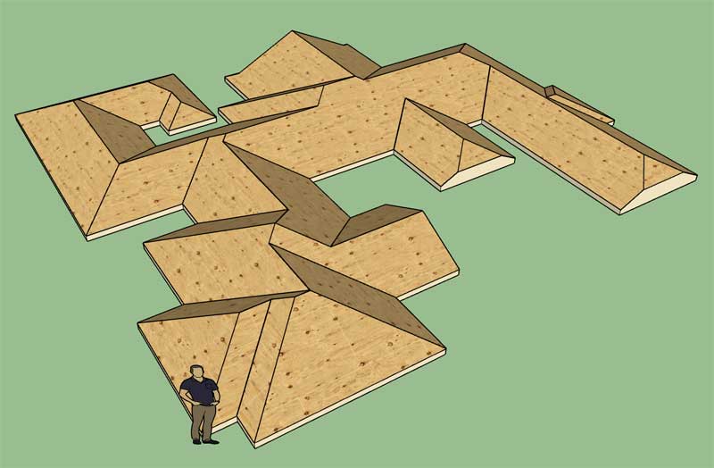
If you look closely at a roof primitive and the edges that constitute that primitive, immediately a number of things jump out at you:
1.) All of the horizontal edges that are at the same Z height as the top fascia line are roof perimeter edges or "fascia edges". We do have to make an exception for the half hip though, since its fascia edge will be elevated above the eave height.
2.) All of the edges with vertices below the fascia Z height are irrelevant and we won't be needing those.
3.) If we look at all the edges coming off of the perimeter vertices (we can find those easily enough by comparing against our perimeter points array) it is apparent that the inside angle between two fascia edges will determine whether the edge is a valley or a hip. If the angle is less than 180 deg. then it is a hip. if the angle is greater than 180 deg. it is a valley. If the edges belong to a gable or half hip roof plane then they will be rake edges, rather than hips or valleys.
4.) Next we grab all of the remaining edges where the height of the start and end vertices are equal. These will form ridges. An exception must be made for dutch gable and the half hip. So it is best that we eliminate those edges first.
5.) Fortunately, there are no such thing as flying valleys, only flying hips. By process of elimination the remaining edges will all be flying hips. Flying hips are interesting because they always begin where a valley and ridge intersect and they end either intersecting another hip/flying hip at a ridge or at a peak with possibly multiple hips coming together at a point.
We basically dump each edge in the primitive into a hash so we have ourselves a quick lookup table for each edge that we can access it for future operations (ie. cutting rafters).
When the roof corner angles are all orthogonal (90 deg. or 270 deg.) the algorithm for the rafter framing should be fairly simple. However when you throw in non-orthogonal angles (ie. octagon roofs) things become more complicated and there needs to be some logic to deal with these scenarios specifically.
Another reason that I need to classify the edges is that the width of the valleys, hips and ridges may not be equal, which will impact the trimming of the rafters as they intersect these members.
And that is all the magic there is to it. I think the key breakthrough I had back in May (when I figured out my straight skeleton algorithm) was that I realized that once I somehow generated the roof primitive the rest would easily fall out. Previously, I was trying to mathematically calculate all of these vertices and edges, which turned out to be incredibly difficult and ultimately a dead end.
I now have a coherent plan of attack.
-
I've also been giving some thought to gutters. If there are no half hip or gable conditions the gutter will wrap completely around the roof.
Otherwise the gutter will be broken into one or more sections.
Downspouts are more of an issue. With a complex roof the positioning of downspouts needs to be more customizable. I would like to implement a system where the user can select standard locations to position downspouts along a gutter run. For instance at either end or at the middle, this should provide enough flexibility for most situations.
-
@medeek said:
I've also been giving some thought to gutters. If there are no half hip or gable conditions the gutter will wrap completely around the roof.
Otherwise the gutter will be broken into one or more sections.
Downspouts are more of an issue. With a complex roof the positioning of downspouts needs to be more customizable. I would like to implement a system where the user can select standard locations to position downspouts along a gutter run. For instance at either end or at the middle, this should provide enough flexibility for most situations.
Are you going to provide an interface where parameters will be set, to be adhered to, for the sizing of gutters and downpipes (thus relating to number of) based on the plan area (not actual, but measured perp from above) of the roof served?
-
Tutorial 16 - Introduction to Complex Roofs (19:42 min.)
I did forget to mention the "Edit Outline" function which can be initiated by right clicking on the roof assembly. However, if you have a number of customized roof planes the results may become unpredictable, especially if the the outline is dramatically changed. The feature will need some further refinement.
-
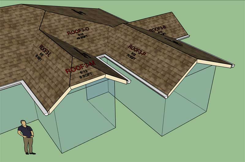
First look at a gutter fully wrapping a complex (hip) roof:
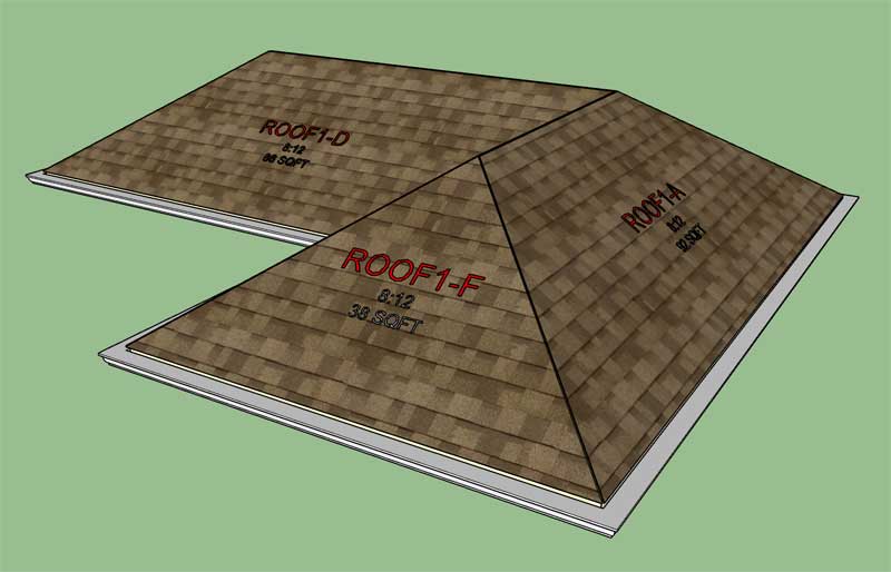
Note the 3/4" offset from the sub-fascia since I have soffit and fascia enabled. The 3/4" thick fascia is not drawn yet, hence the gap.
I've also set my vertical offset to 1" for the gutter.
-
Version 2.5.6 - 10.11.2019
- Added gutters for complex roofs.
View model here:
3D Warehouse
3D Warehouse is a website of searchable, pre-made 3D models that works seamlessly with SketchUp.
(3dwarehouse.sketchup.com)
On this particular model I've employed a vertical offset of 1" and a gutter extension of 1.5" with a K5 style gutter, other gutter styles available.
I have not enabled downspouts yet as I need to come up with a better system for handling these. I think I have a new system figured out but I need to work on the details before I'm ready to implement it.
-
The problem with complex roofs is that I am only scratching the surface right now. There are quite a few permutations that are possible that are quite common with many residential designs that I still cannot handle with the current complex roof module.
Consider this relatively simple example:
3D Warehouse
3D Warehouse is a website of searchable, pre-made 3D models that works seamlessly with SketchUp.
(3dwarehouse.sketchup.com)
With this case the fascia is at two levels. At the back corner on roof plane A you have what I call a 3/4 Hip (kind of hybrid between a half hip and a hip, one side is a hip and the other is technically a half hip). This causes the fascia line to rise by 24".
Where roof plane E meets roof plane D, you have one roof plane dying into the other and creating a "Flying Valley" and the other roof plane terminates at the wall below (a partial gable end?).
I guess I was wrong there are "flying valleys" after all.
The problem with trying to construct this particular example with my proposed secondary roof module is that its a little more complicated than that. Rather than two separate roof assemblies the roofs are technically merged. Also the 3/4 Hip configuration kind of requires that the roof assemblies are one construct.
This example really has me scratching my head right now.
What does jump out at me is that when you are dealing with an inside corner (angle between walls is greater than 180 deg.) the roof planes die into each other creating a partial gable and a flying or hanging valley.
When you have an outside corner (angle between the walls is less than 180 deg.) you then end up with a 3/4 hip. Two additional solutions might be a gable or half hip with unequal legs. If you were to keep making the setback of the half hip larger eventually it would degenerate into the 3/4 hip where one leg is now a hip roof.
-
My original restrictions on the placement of gable ends are too tight. In order to created roofs where you may have a gable on a gable we need to relax things a bit or at least change up the conditionals:
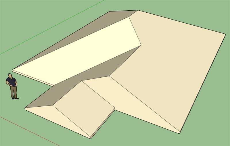
This further complicates each building element or at least opens up possibilities which did not exist before so I will need to add additional logic for sheathing, cladding, sub-fascia and gutters.
Who said complex roofs were going to be easy.
-
Another variation of the gable roof study:
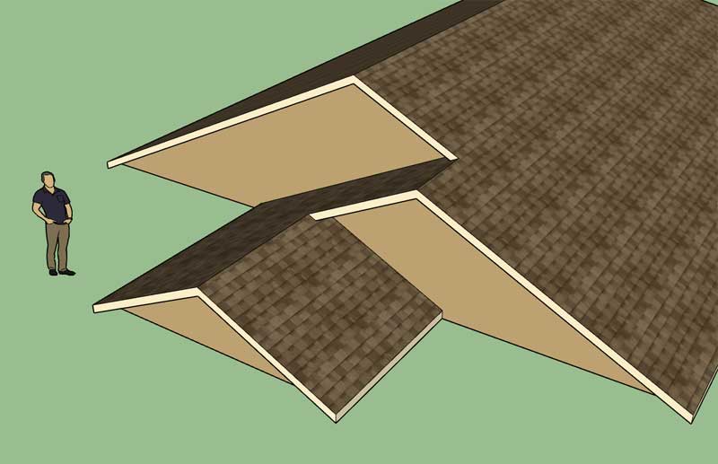
Gables ad infinitum...
The one thing that jumps out here is that gable roof planes cannot be adjacent to each other (or other variants like dutch gable or half hip configurations), gable roof planes are separated by hip planes. Additionally, I will limit the gable option to orthogonal roof planes only (corners must be 90 or 270 degrees).
There is always on more thing to add, at some point I hope to have conquered this beast.
-
When you raise the fascia line along a segment of the roof inevitably it must return to same level since a roof is a closed loop. See model here:
3D Warehouse
3D Warehouse is a website of searchable, pre-made 3D models that works seamlessly with SketchUp.
(3dwarehouse.sketchup.com)
I think I can make this work but I'm going to have to drastically change my algorithms to allow for unequal fascia/gutter lines.
The other interesting thing with all of this is that the fascia line could step up and down multiple times around a roof.
Another observation is that only hip roof planes technically step up or down, gable roof planes/edges are controlled by the adjacent hips.
Advertisement


