3D Truss Models
-
I see the plugin was listed on extension warehouse yesterday, I'm sure between the Sketchucation platform and extension warehouse platform you will have quite an audience of prospective clients.
-
With the truss plugin I have been primarily focused on typical MPC wood trusses however the potential for other truss types does exist. I'm wondering if some of the more exotic timber truss types can be codified in a similar way so that one can generate possible configurations and experiment with their design.
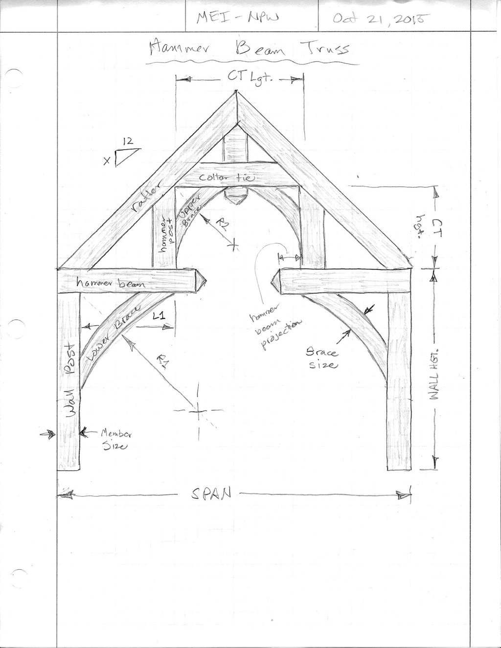
One interesting truss type that comes to mind is the Hammer Beam truss/frame as shown below:
Some other variants (and probably quite a few more):
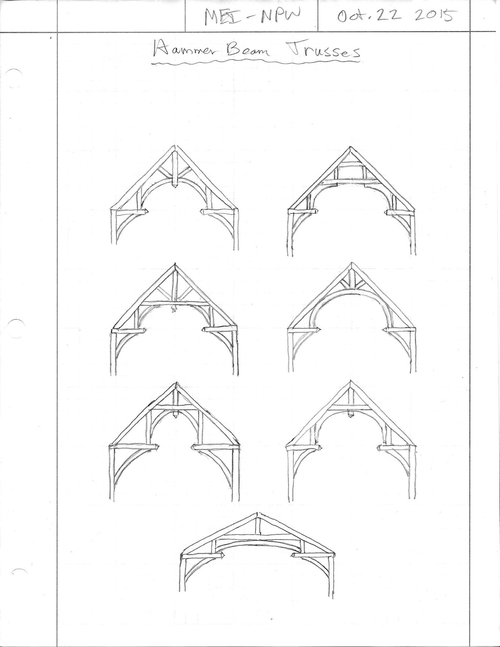
Any thoughts on these types of trusses? Would there be any interest or need? Would it be appropriate to add these types of frames/trusses into this plugin or would a separate plugin be a better option?
-
Joe wood, bmike and otb designworks are members here who might be able to give you an idea on use of more elaborate trusses. Sonder also does uses that sort of thing.
-
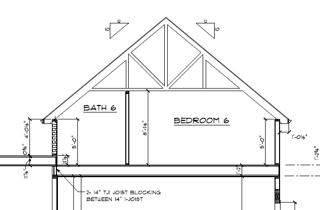
I used this style of truss awhile back. Really like it since it simplified the construction not having to use a ridge beam.
And yes to timber trusses.
-
@studio43 said:
I used this style of truss awhile back. Really like it since it simplified the construction not having to use a ridge beam.
A tail bearing Howe truss.
My first question is what prompted the use of this particular truss type? I'm assuming that the wall or residence height was limited at this cross section.
Second question, can you send me (email) any documents (PDF, JPEG etc...) of the actual truss drawings generated by Alpine or Mitek that I can study and determine the methods used in generating this truss type. I've seen a few of these but I don't have any good information on them so I don't yet know how to design them or at least what is industry standard practice with this truss type.
In particular I am interested in the splice of the top chord where the larger TC tail bearing member meets the smaller TC member.
I'm also interested in the birds mouth cut at the point of bearing. What happens with a 2x4 or 2x6 exterior wall?
Sorry for all of the technical questions but this is what makes my plugin worth having IMHO. The designer needs the truss drawn accurately so that when the plans go to the truss manufacturer and out to build there are no surprises.
This would be a new family of "common tail bearing trusses".
Obviously I've only just scratched the surface, here is a good light read on trusses with some nice visuals:
http://www.ebsbuild.com/wp-content/uploads/pdf/trusses/at-buildersguide.pdf
-
I was thinking about adding the scissor truss family to my SketchUp plugin until I realized that the calculation of the scarf of the bottom chord was a bit more complicated than your typical common truss with a zero pitch bottom chord. When I actually sat down and did the math it became clear how much more complicated it actually was. If anyone cares to check the math I would be very grateful. I will probably run it into AutoCAD tomorrow and graphically check the geometry against the equation, they should give the same result.
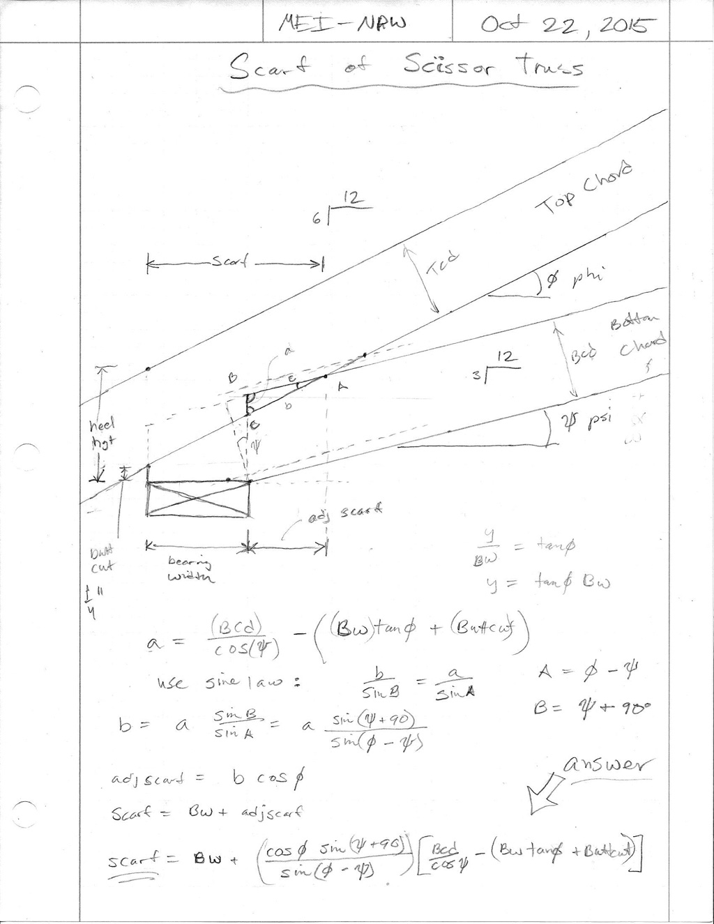
Notice how the bearing width factors into the scarf and ultimately affects the entire design of the truss (web placement, panel lengths). This is why the truss companies require the bearing width before they can quote you on scissor truss package.
Makes one appreciate computers a little more when you realize that the software, once programmed, can take care of all these detailed calculations without us giving it a second thought.
-
I'm appreciating the eagerness with which you are developing this plugin.
Would you post a notifier here every time a new version is released?
-
Medeek
That style of truss allowed us to lower the bearing height as part of the architectural design. A sort of story and half design common in my area. Traditional stick framing is more complicated. Typically, adding a ridge beam is the preferred way to keep the walls from spreading out. This style of truss does away with that ridge beam. Another benefit is the cost for using this truss is much lower than stick.
I still have the truss drawings for that project and will dig in to the file and find them.
-
@juju said:
I'm appreciating the eagerness with which you are developing this plugin.
Would you post a notifier here every time a new version is released?
I can do that.
Creating this plugin has been a bit of fresh air for me, definitely a change up from my regular fare of local engineering projects. I'll probably need to pull back for a few days and focus on my regular clients but it is hard not to dabble with this whenever I get a moment.
What makes this so exciting is the speed with which I am able to add new geometries and features. Programming my other truss calculator is much more tedious and time consuming (html, SVG and perl).
-
The equation was spot on, my faith in trigonometry is restored:
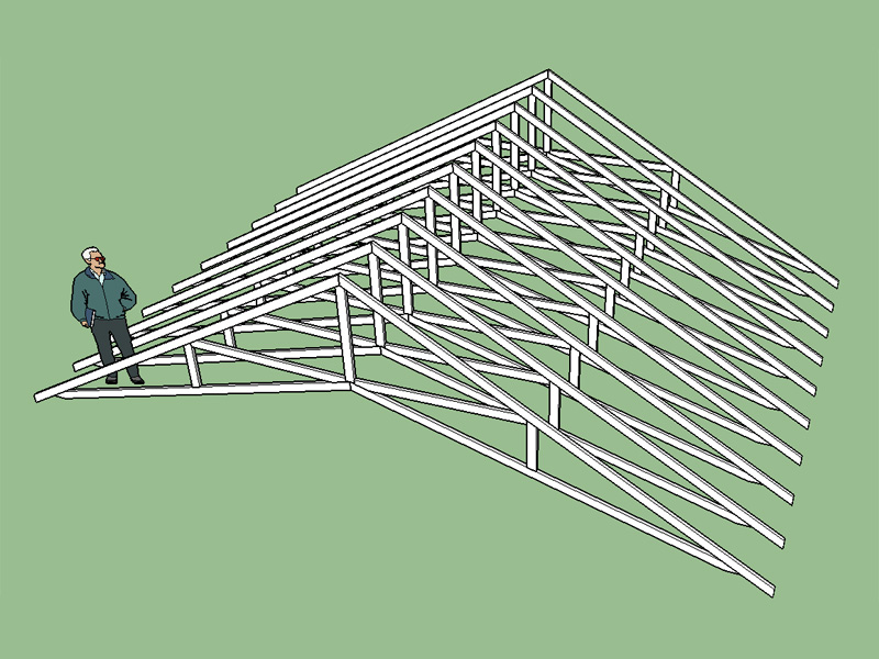
Version 1.0.5 - 10.24.2015
Added Scissor truss type, configurations: (2/2), (4/4).
Metric input enabled for scissor truss types.In certain instances the scarf length of the bottom chord becomes less than the bearing length, the logic checks for these cases and inserts either a 3.5 or 5.5 heel wedge as required.
-
I've been adding truss types/families as requested by users and member of this forum and others. The list of families continues to grow and my current todo list is:
Common (tail bearing)
Dual Pitch
Gambrel Attic
Mono Scissor
Floor
Vault or Cathedral
ClerestoryOf course this is only a small sampling of the potential truss families and types.
Beyond the basic truss families I would like to have the plugin also have the option to generate gable end trusses for each family was well as all the raised heel variants (wedges, sliders and verts). The gable end trusses are more complicated than originally thought since structural and dropped gables also need to be included. Dropping the top chord 1.5 or 3.5 inches also further complicates the matter since this change in drop involves a different geometry.
Instead of dumping the trusses at the origin I've had requests for the ability to locate the truss array based on selection of a bounding rectangle. I need to give this some serious consideration since it will probably make this plugin that much more valuable and efficient to use.
I'm also thinking about more complex situations such as entire hip sets and valley sets.
Then there are transition gable end trusses and transition gable end monopitch trusses, which may or may not be worth adding.
On a completely different note I've also considered adding in timber framed trusses (ie. hammer beam trusses etc...) however I think a separate plugin dealing specifically with timber framing would be more appropriate.
I have no idea how long it will take me to accomplish all of this. I have become faster at adding truss types as I've settled into a standard procedure for adding each truss family. However, each truss family takes at least 2-3 hours to add in and then that only includes 1 or 2 configurations whereas I should probably add at least 4 to 5 configurations for each truss family.
I will probably continue to chip away at this as time allows and as interest grows.
As you can probably tell trusses are intensely interesting to me and that will probably keep me going regardless of the interest levels.
-
On the SketchUp board I've had a request to make the member size parametric so that they can be changed/updated after they are created. I did not know or don't know if SketchUp has parametric capabilities. Any thoughts on this?
-
@unknownuser said:
don't know if SketchUp has parametric capabilities. Any thoughts on this?
With Dynamic Components or heavy ruby coding?

-
Version 1.0.6 - 10.25.2015
Added floor truss type, Modified Warren - System 42.
Metric input enabled for floor truss types.
Top and bottom bearing option enabled for left and/or right end of floor trusses.
Ribbon cut option (top) enabled for left and/or right end of floor trusses.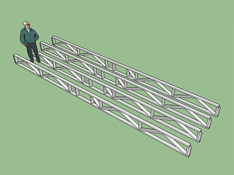
One central chase that can be position relative to the left end of the truss. If the chase becomes closer than 1/4 the span to either end it will flag the user and re-position. Also some logic to check the chase size to span ratio and absolute max. chase size (24").
System 42 or 32 floor trusses using the modified warren configuration which seems to be the most popular for this type of floor truss. Top bearing configuration includes an additional slider for extra strength and a vert. Note the change in diagonal directions when comparing a top to bottom bearing floor truss, I was not aware of this until studying them in some detail. Typical panel length is 28" but this can also be set by the user to any value.
I figure if you need more than one chase it isn't to hard to manually edit the component and copy a couple of the vertical members over and then trim out the diagonals.
-
@pilou said:
@unknownuser said:
don't know if SketchUp has parametric capabilities. Any thoughts on this?
With Dynamic Components or heavy ruby coding?

I've been looking at dynamic components and the API documentation seems rather sparse. There are a number of forum posts on this topic but so far it seems to be just beyond my grasp.
-
Floor trusses 40' span, 60' bldg. length, 24" deep.
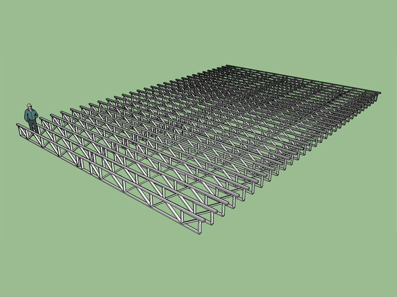
Notice these are top chord bearing trusses with the diagonal webs reversed from the bottom bearing trusses in the previous post, this is by design.
-
Various configurations of a vaulted or cathedral truss:
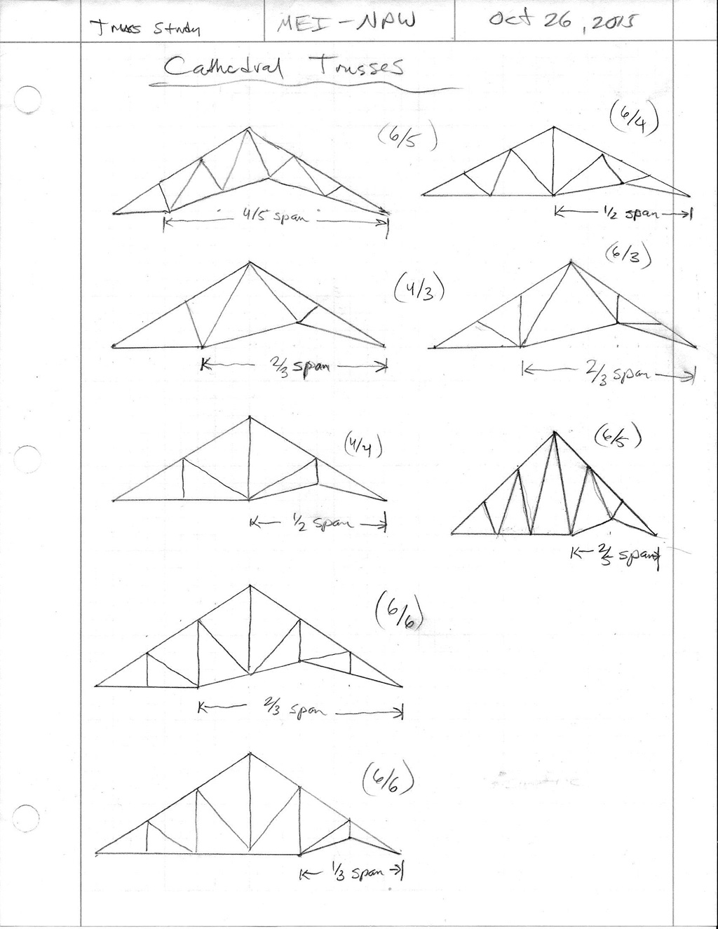
-
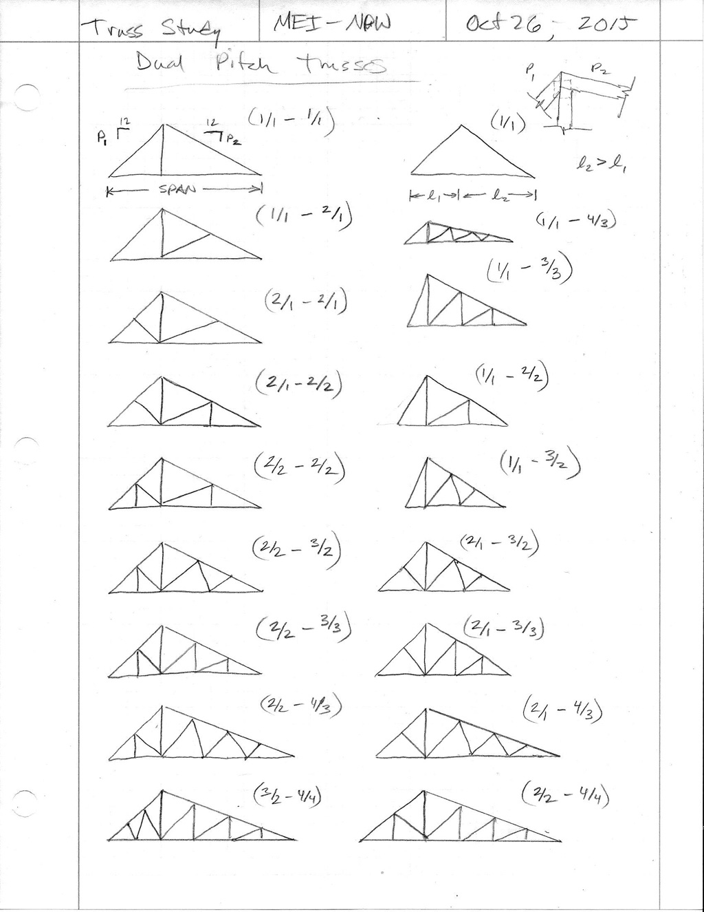
Various configurations of dual pitch trusses:
-
have at look at "parametric_grid.rb" and "parametric.rb" from sketchucation Plugin Store...
john -
@driven said:
have at look at "parametric_grid.rb" and "parametric.rb" from sketchucation Plugin Store...
johnThank-you for the information. I will be looking into this further.
After using the housebuilder plugin and my own I've determined I am lacking in two areas:
Post Configuration: Ability to modify the component once it is created. It would be nice to make it a dynamic component and adjust any and all variables.
Positioning: It would be really nice to drop the truss set right into place by clicking the location with the mouse.
Advertisement


