3D Truss Models
-
Very enlighting video!

else (Always : https://trussfr.weebly.com

Truss Type = Type de Fermes
(not sure to translate all names of this little list of part of trusses)
King Post
Queen Post
Fink
Howe
Fan
Mod Queen
Double Fink
Double Howe
Mod Fan
Triple Fink
Quad FinkOut-to-Out Span = Portée Hors tout
Top Chord Angle = Angle de Corde Supérieure (?)
Overhang Left = Porte-à-faux Gauche
Overhang Right (Same as Left) = Porte-à-faux Droit (Identique au Gauche)
TC Size = Taille TC (? à définir)
BC Size = Taille BC (? à définir)
Web Size = Taille (?)
Ply Thickness = Epaisseur du Pli
Raised Heel (No, Yes) =Talon surélevé (?) ( (Non, Oui)
Heel Heigh = Hauteur du Talon (?)Bldg.lenght = Longueur Bâtiment
Truss Spacing = Espacement de Ferme
Gable End Trusses (Yes, No, Front) = Poutrelles d'extrémité (Oui, Non, Face Avant)
Gable Stud Spacing = Espacement Goujons de Pignon (?)
Adv. Roof Options (Yes, No) = Options Avancées de Toit (Oui, Non)PS
Does the Messages' window data is self-adapting to the length of words ? -
Thank-you Pilou, I will add these phrases into the language file.
Yes, the SU menu automatically adjust for the length of the words so even though French is often more verbose than English it does not matter. I've noticed though that Russian has some problems rendering in the SU menus.
I would have liked to see the video dive into the advanced menus more but I realize there is far too much material to cover in such a short video.
-
@unknownuser said:
Yes, the SU menu automatically adjust for the length
Excellent!

What is BC and TC size ?

Minor Roof Family = Famille de Toit Secondaire
Gable Dormer = Lucarne de Pignon
Hit Dormer = Lucarne de Toit
Shed Dormer = Lucarne de Hangar
Gable Roof Minor = Pignon de Toit Secondaire (?)
Hip Roof Minor = Lucarne de Toit Secondaire (?)
Dutch Gable Roof Minor = Pignon de Toit Hollandais Secondaire (?)The (?) does not signify that is forcefully false but can maybe be enhanced!

Else works fine!

-
BC = Bottom Chord
TC = Top Chord
Web = Internal (web) members of truss -
Thx for the Infos!

-
The license registration module was causing some problems in isolated cases so I've released a sub-rev. 2.1.1b to address that issue.
If you are trying to enter in your serial number and it does not appear to take, first verify that you are not entering in any leading or trailing white spaces if that does not solve the problem you may be encountering the issue at top, in that case download the latest version which should address the issue fully.
-

Valley set chest => Panel de NoueStepdown Hip Set => Panel de Panne de Rive Inclinée
Terminal Hip Set => Panel de Sablière
Northeast Hip Set => Panel de Linçoir
Metal plate connectors = Connecteur Métallique Plat
Gusset = GoussetWeb = Membrure
Web = Fiche & Contre-Fichein this following Schema "Chantignole" is false : must be "Arbalétrier" !


-
This week has been a bit tough for me to get any meaningful work done on any of the plugins, too many Christmas concerts, parties etc... but I guess its for the better. This weekend I will try to get out the update for the heel blocking and an update on the translations.
-
Version 2.1.2 - 12.18.2017
- Enabled vertical and angled heel blocking within the advanced options for truss roofs.
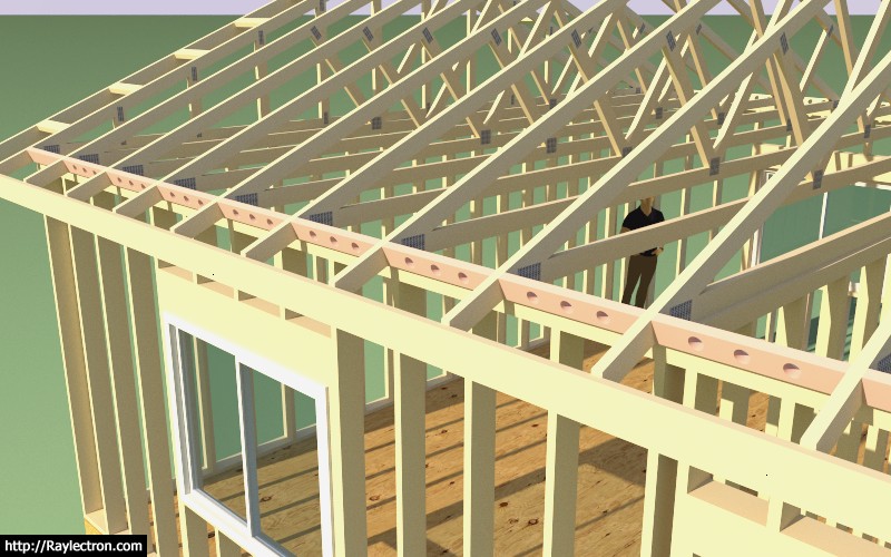
If you choose to enable vent holes the heelblock menu will prompt for the hole diameter. The vent hole algorithm will place vent holes in the heel blocking per the truss spacing:
< 12 in. = 1 vent hole
< 16 in. = 2 vent holes
16 in. or greater = 3 vent holesLet me know if this makes sense, I can always modify it to meet any criteria. If this sort of thing varies a lot per locale I can also make it more user definable.
-
This type of heel blocking is very typical in my locale (Western Washington State):
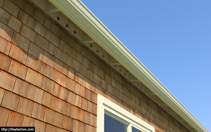
View model here:
3D Warehouse
3D Warehouse is a website of searchable, pre-made 3D models that works seamlessly with SketchUp.
(3dwarehouse.sketchup.com)
-
To end off the year with a bang and to thank our truss plugin clientele I have decided to reduce the license renewal fee for the Medeek Truss Plugin to $10.00 USD. This promotion will run until the end of this year (Dec. 31, 2017) and then the renewal price will return to its usual price of $20.00 USD.
This year has been very busy with further developments of the truss and foundation plugins. I am looking forward to the new year and another full year of new features and even new plugins and tools.
I've really appreciated all those who have actively contributed to the recent developments of the plugin, especially the translations.
A Merry Christmas to all and a Happy New Year.
-
Sorry but a more complete French translation will be at the beginning of the next year : no more free times for the moment!

Have happy new year!
-
Just some minor bug fixes for 2.1.2b, I will probably address some other minor issues brought to my attention in the next couple of days.
-
I've been thinking about adding in the option to show H1 ties for rafters and trusses:
.jpeg?quality=80&u=cjmyin&crop=0)
I've seen them mounted both on the exterior and the interior with the flanges facing both inward and outward, four possible configurations. Any preference on how these are typically installed. I'm sure there is probably not much call for these but it isn't a big deal to add in the option for those that would like to use it.
I am currently featuring Simpson Strong-Tie hardware in the Truss Plugin, not because I am specifically endorsing their products or the brand but because that is what I am most familiar with and their products are readily available in the US and Canada. Mitek also makes comparable hardware and probably has better availability outside of the US and Canada.
I'm also thinking about allowing the user to choose between and H1 or H2.5A:

-
I've had a number of new and existing clients who are running SU2018 on MacOS who are reporting that they are unable to save global settings for the plugin. The problem is that no one is seeing any errors generated in the ruby console so I am currently at a loss on the exact problem and how to solve it.
Has anyone seen a similar issue and have been able to resolve it?
The code to write the global settings is very simple, an example below:
# Writes Materialsoption Setting

@Materialsoption_write_result = Sketchup.write_default "MEDEEK_TRUSS_PLUGIN", "MATERIALS_OPTION", @Materialsoption_new
Why would this stop working on SU2018 running on MacOS?
-
Per the discussion in my previous post, I've shown two H1 Clips both attached to the exterior of the wall. One is oriented with the flanges inward and the other with the flanges outward. Notice the placement of the bird blocking next to the clips. My question is what is the preferred orientation of the H1 clip?
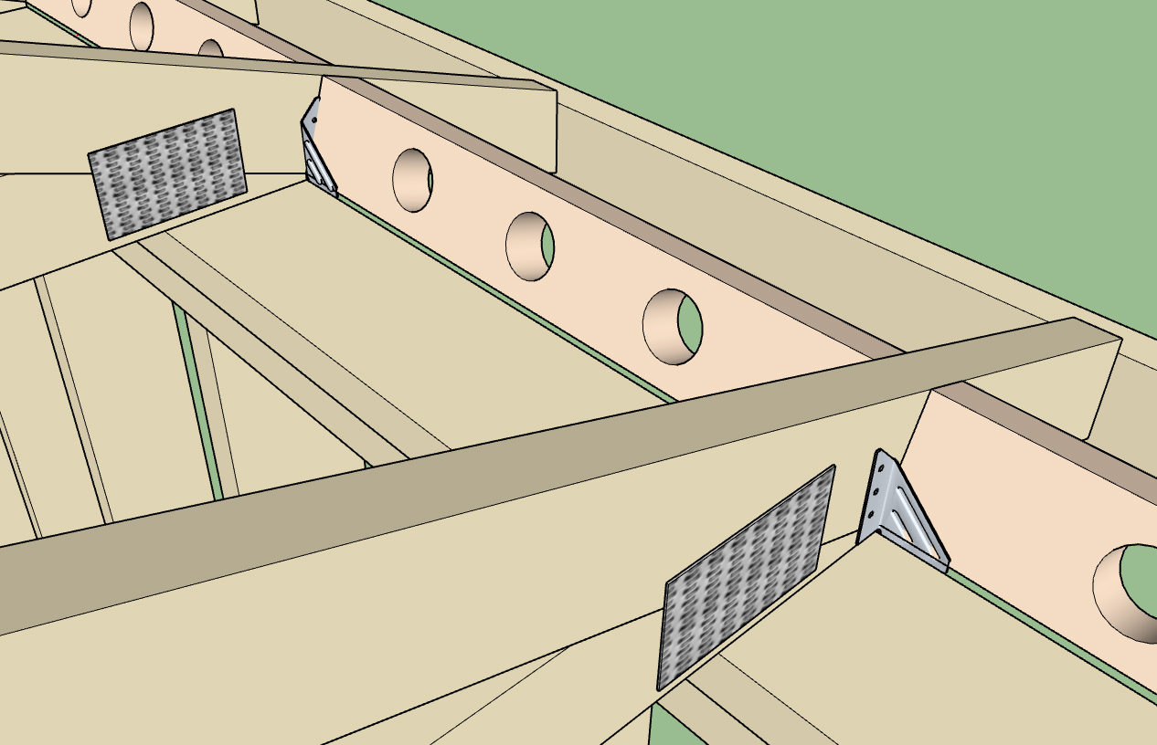
Model can be viewed here:
3D Warehouse
3D Warehouse is a website of searchable, pre-made 3D models that works seamlessly with SketchUp.
(3dwarehouse.sketchup.com)
Based on my discussion with other engineers and architects so far it would seem that the best placement of the clips is on the exterior of the wall as shown.
-
Testing out the H1, H2.5A and H10A hurricane clips:
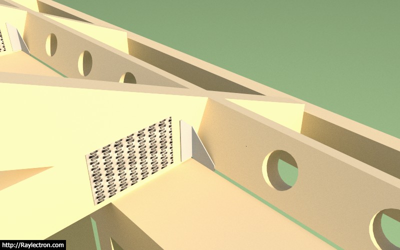
The plugin is now able to insert hurricane ties. I've currently set it up so that they are installed on the exterior of the framed wall with the flanges inward. Shown below is a Simpson H1 with angled vent blocks.
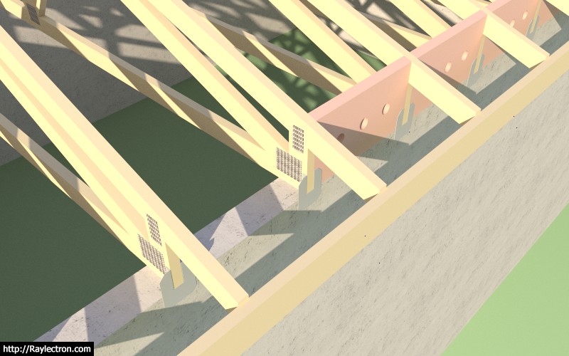
Here is an example using the Simpson H10A with vertical heel blocks and a raised heel truss connected to a masonry or concrete wall.
Ignore the vent holes in the blocking, I will provide additional options for venting in the near future.
Note that plugin automatically inserts these ties into the truss component, one on each end. The simplified H10A component is based on the official Simpson model found at the 3DWarehouse and is dimensionally accurate but with a much lower polygon count and hence much more lightweight.
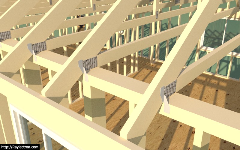
Here is an example using the Simpson H2.5A hurricane tie. The upper tab is facing outward by default. The tie on the other end of the truss is positioned on the opposite of the truss to this one.
I will roll it out for trusses first and then rafter roofs at a later date.
I've specifically created simplified, lightweight versions of the hardware, so that the polygon count is minimal. With so many components I think it is imperative that the model is carefully constructed so as to minimize its polygon count and keep it as lightweight as possible.
-
Version 2.1.3 - 12.31.2017
- Enabled hurricane ties for fink and howe common trusses.
-
Medeek Design Inc. - Medeek Truss Plugin Vendors
Medeek Design Inc. - Medeek Truss Plugin Vendors
(design.medeek.com)
List of material suppliers and vendors featured in the Medeek Truss Plugin.
-
Does anyone have some shop drawings of a dutch gable or half hip roof? I am looking at adding in the truss sets for these two variants.
Advertisement


