Problems with a half-torus
-
No I don't mean unsoftened lines. You see how your base has segmenting? I had that but all the segmental radii were on the top of the base and gave me enough grief to make me bin it. I'm on the case again, at least I will be after I've had some sleeps, it's 0730 now and I'm toast

-
Yep, what Box said...the best way is to optimize the segments at the beginning. That said, you can use Netfabb Basic to quickly decimate (reduce the # of polygons) an existing model with out having to re-draw the whole thing.
Here's how: open model in Netfabb, Right click > Level of Detail > Choose something like 50%.
-
@d12dozr said:
Yep, what Box said...the best way is to optimize the segments at the beginning. That said, you can use Netfabb Basic to quickly decimate (reduce the # of polygons) an existing model with out having to re-draw the whole thing.
Here's how: open model in Netfabb, Right click > Level of Detail > Choose something like 50%.
It must be something like Netfabb my mate's brother had to use for this last print, he ran it through some jiggery-pokery and took the file size down by 90%.
I'll do this version again on night shift tonight with all your suggestions for minimising and see what happens, thanks again Marcus and Box

-
I've just lashed one up tonight, with fewer sides/segments the .stl rolls in at 1.8mb, much better. I'll email it off for printing now.
-
Nice and clean! Show us some photos after the print is back...
-
Yep, a very nice bit of modelling there. Well done.
-
The strengthening of the throat-base was giving me some grief until I had a eureka moment and put the channels for the air vents underneath. Took about 20 minutes to draw, a far cry from a month ago when it took me 8 hours to get an outline

-
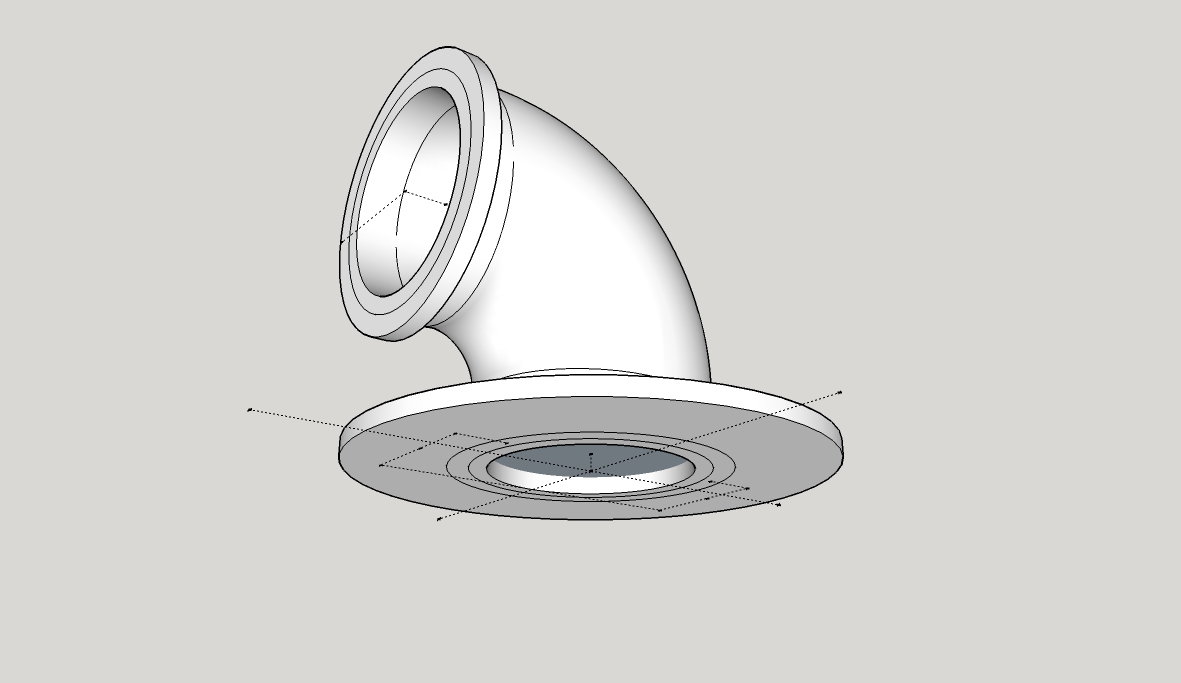
I wonder what's wrong now... It's a long night on shift and started drawing an elbow, it's an exercise really with the general (virtual) notion being to mount the bellmouth up out of the way. So I started fiddling and came up with this:

It gave me a bit of bother trying to draw the support flanges, the result being it's not solid. I'm being told I'll need to manually remove faults. That's my latest problem, I've duplicated and scaled up trying to use the 'Dave R' technique but it doesn't work, SolidSolver unable to fix it. Anyone for some guidance on this one?
-
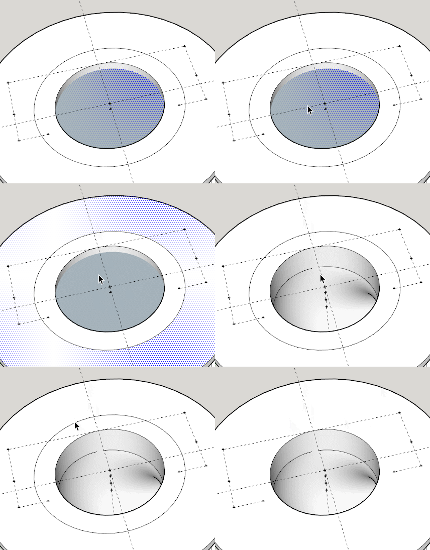
If you intersect the top face of the flange with the collar you can remove the face you can see in the tube. Then a bit of cleanup of some stray lines and it is a solid.
I can give it to you fixed if you want it.I just noticed it is a group, so edits on the big one won't flow to the small one.
-
Oh fiddle! I should have done it as a component....
 I'll try and figure out what you mean Box, I may be back soon...
-
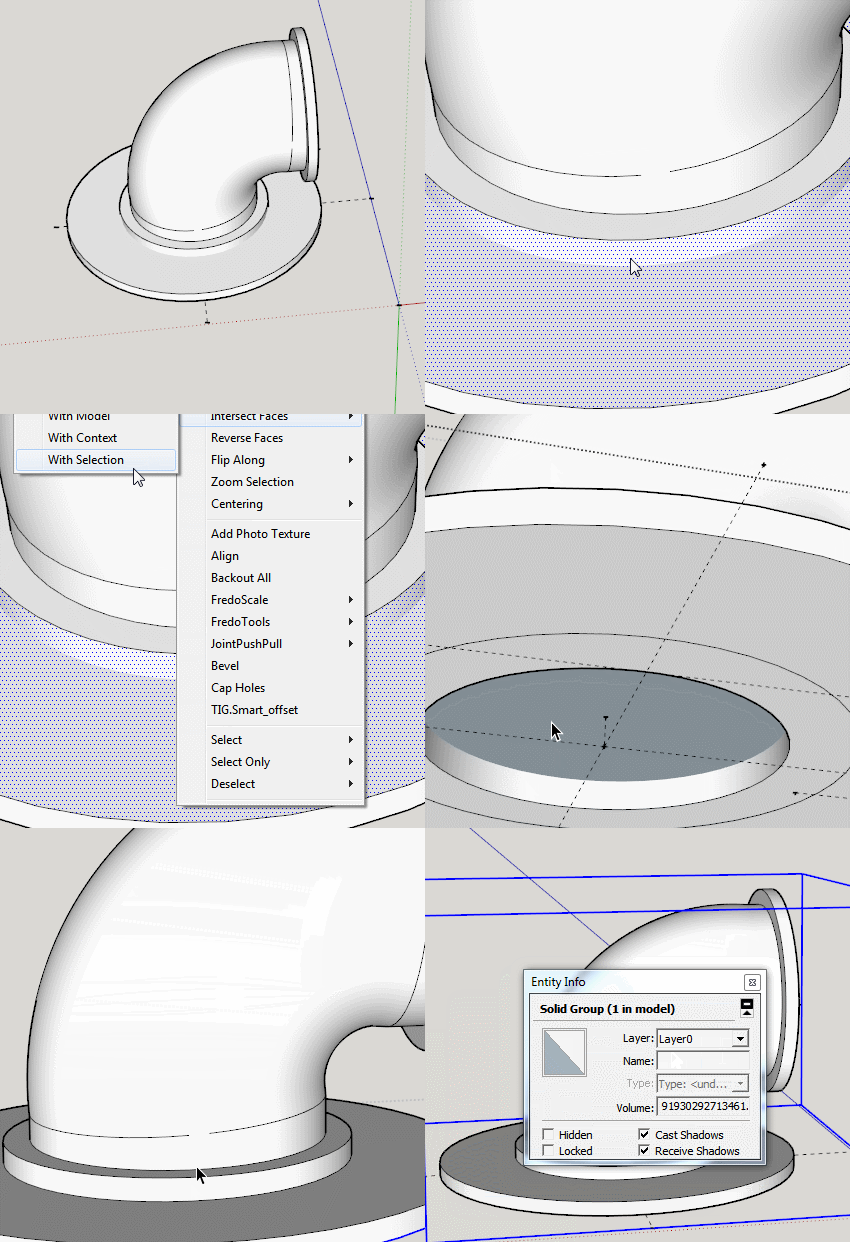
Strewth! How do you intersect them? There's a trio of choices, with face, with model and with selection, none seem to work.
-
-
Here, I'll give you this gif, and see how you go.
But remember to make it a component this time.Edit:if you are wondering what the first context menu was, it was just the intersect face one, but it was off screen so a moved down and did it again to get it where you could see it.

-
And I thank you once again Box, I did what you said, couldn't see what you could see to understand why it worked bu the result is solid!

-
On your original when you look into the pipe you see a blue face, this it the back side of the top face of the flange, so by intersecting that face you can remove the part blocking your airflow, and then removing the other edge/ring gets rid of an internal face.

-
I knew immediately I'd have internal face when I pulled 'backwards' didn't know to get rid though. I do now
 Onwards and upwards, time of home soon for some sleepsssss. Once again, TVM Box.
 -
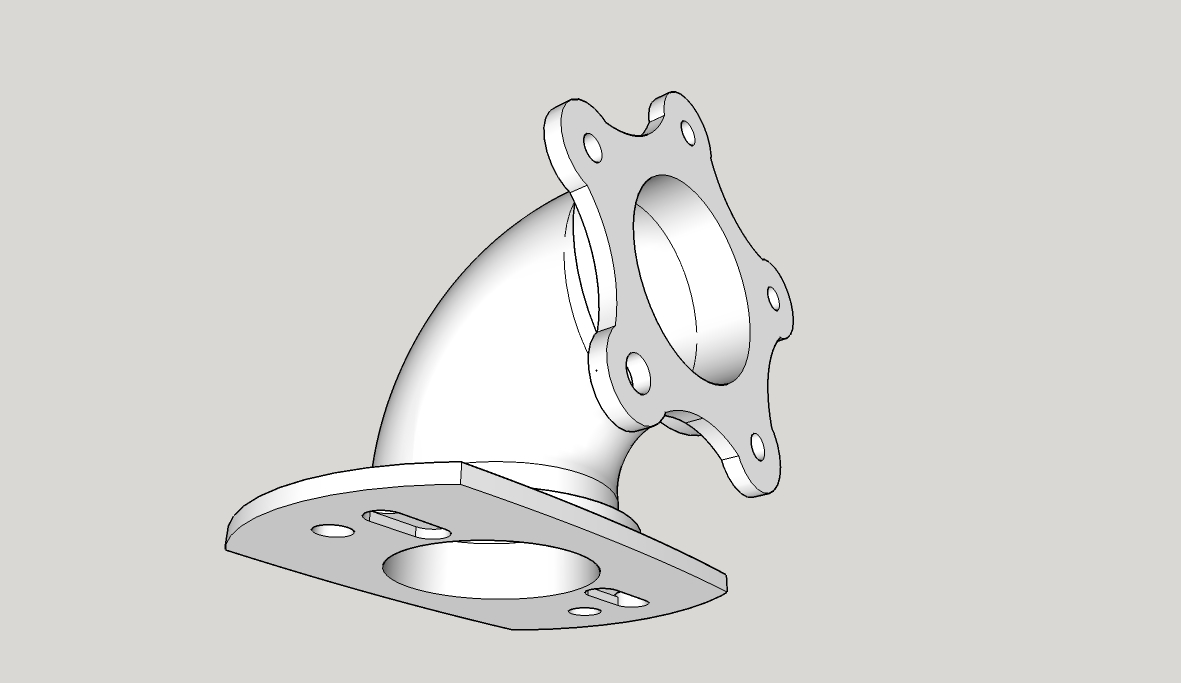
Been playing again tonight and seem to have nailed it


Now to get rid of the five star mount and think about how to draw a snap-on clip type system. I've drawn loads of bellmouths of various sizes; it'd be really cool to be able to clip-on clip-off different ones and be able to compare the difference in the torque/power response immediately

-
Superb, Teig! It's neat to watch your progression from the beginning of the thread to now

-
Indeed is is good to see.
Have you thought about a keyhole type slide fitting.
Slide it on and a simple quick release split pin to lock it. -
Or R-pins for more simplicity? Yes, good idea. I've been looking around at plastic snap-clips for ideas but that might be simpler.
Advertisement


