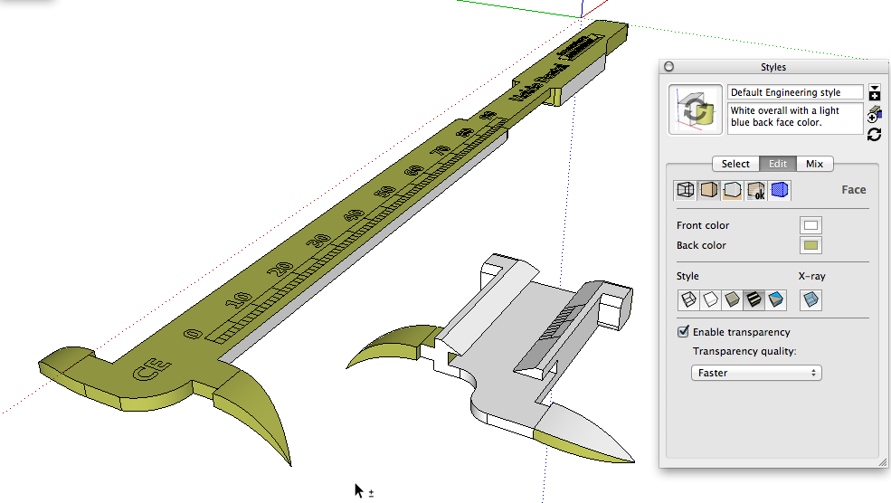
Aparently not a solid form?
-
-
Thomthom's Solid Inspector will find errors for you to fix.
Tig's Solid Solver will attempt to fix errors for you. -
Wow!
Many Thanks,
I think I've just discovered my new favourite Forum!So the tool works fine!
Now I've got a different problem...
The tool finds all these loose ends. Killed them all.
But these are a set of callipers with hash lines on the surface of them for taking readings. So now I've got to somehow make hash lines without them apearing to be "loose ends".
any suggestions?
Thanks
-
Those hash lines wouldn't show in a 3D printed model anyway because the printed doesn't print edges. Make your hash marks as tiny rectangles that you push into the surface. How large you make them and how deep you push them in will depend on the printer resolution.
-
Thanks for the quick answer
These calipers will be machine milled in INOX stainles steel and laser engraved so not realy the problem. I've solved that problem now anyway.
The problem I still have now is that despite a clean bill of health from the solid inspector plug in. it still shows no volume and will not export. via the IGES Export plugin
"Model contains non-solid elements, these will not be exported"
I've saved and restarted SU and rechecked with the solid inspector plug in. Same results, no faults but still not a solid?
Jay
-
Can you attach the model so we can check.
-
Look to see if you have a nested group(s) and or component(s), as Solid Inspector will not alert you to those.
-
Ok,
here it is, in 1:1 scale. I had to scale it down to real size for the upload limit but still same problem...
Thanks again!
-
Because your 3D text components are inside the long bar, the long bar is a nested component as Marcus guessed. That's why it doesn't show as solid.
Just a hint when you are scaling your model up and back down: Don't let it get a long way from the origin. You model's components are about 28 meters away from the origin after you scaled down. That can cause problems. Use the same scale handle to scale down as you did to scale up. Or better, use the Tape Measure tool instead.
-
And it's inside out.
-
@box said:
And it's inside out.
Well, not all of it.


Good point, though.
You need to make sure you keep face orientation corrected as you go.
-
See if this is closer to what you want. I didn't do the small numbers at the right end of the caliper. You'll still have to decide how to handle the lines but if those things are to be laser etched, maybe they need to be made in a file separate from the 3D model. Maybe the text and scales should be done in something like Inkscape.
-
Ok Great,
Are the way the lines now OK for a solid or is this going to cause problems. I suppose I could imprint them as tine rectangles.
I'll check up on scaling with the measuring tool.
What exactly do you mean by face orientation?
I'll read up on that later if the answer should be obvious.
I know I can invert the faces but never realy worried about that. How do I know which surfaces are outside and which are inside-out?Thanks for the repair.
Jay
-
The lines will probably be OK but there's still the small numbers that need attention. I didn't finish the repair.
Scaling with the Tape Measure tool: Click on one end of a known length, click on the other end of the known length. Type a new dimension. Hit Enter. Read the Online Help files for more.
Face orientation is important. You want to get in the habit of doing good housekeeping as you go along. The style you are using makes the difference between front and back faces rather subtle. I changed the back face to green so it would be more obvious. I would suggest you establish your own default style with an easily identified back face color so you can get on them and correct then as needed. I find the green color useful in picking out holes, too. Even very tiny holes are easy to see with the back face color set to green.
-
Good tips. Thank again.
-
The lines will probably be OK but there's still the small numbers that need attention.
What needs to be done to them? should I imprint them like the larger ones?

-
Yes. I left them as individual components but they need to be exploded. Actually they are not exactly on the surface, either so you'll need to move them down onto it after you explode the components. Do that with the bar scaled up, though. It'll make it a lot easier.
The way I handled it when I did the numbers and letters that I did do, is I made a copy of the component, scaled that copy up by a factor of 1000 and did what I did. When I finished editing the component, I closed it to get out of Edit mode and deleted the giant copy. This left the original where it was and the original got edited along with the big copy. Fortunately you are using components instead of groups or that wouldn't work.
-
Just to be clear on why you need the faces the right way around, apart from many rendering programs having problems with back faces, 3d printing needs to know.
Imagine a cube with a sphere inside it, if the back faces of the cube face in and the sphere face out, the printing software knows that you have a cube with a sphere shaped void inside, rather than a solid cube with a solid ball inside it.
-
Ok did the fix on the smal numbers.
You lost me on how you did that, maybe in a couple of years I'll understand that stuff better.
I just deleted the numbers and redid flat numbers directly on the surface exploded them and extruded them.
Probably the long way round but it worked.Just going to check all the surfaces again and try to export it.
Thanks again!
jay
-
What did I lose you on? The copied component thing?
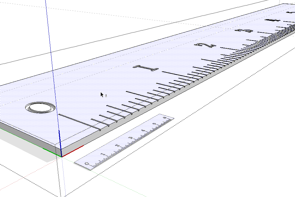
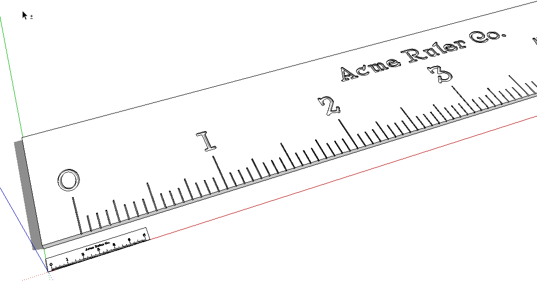
Here I made a ruler component full sized (the little one), made a copy and scaled the copy up (the large one) The large copy is open for editing.

After adding the 3D text for the company name, you can see it also appears on the original copy as well.

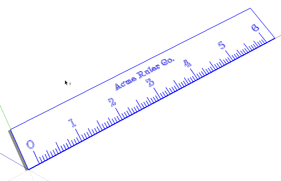
After closing the large one to get out of edit mode and deleting it, Zoom Extents takes us back down to the original one.

You didn't need to redo the numbers. Just finish the job.

Advertisement


