Basics - creating components and pushpull direction
-
Very new to Ruby scripting, so please excuse potentially dumb questions.
I'm trying to write a script to draw timber stud walls. At the moment I'm just trying to get the basics working - bottom plate, stud, top plate as components. Later I'll copy the studs at certain spacings along the length of wall, add nogging, allow custom input dimensions etc, and maybe add features for windows/doors etc with jamb studs, lintels and so on.
Below is the code where I'm at for now. It works, kind of, in that it draws a bottom plate, a stud, and top plate.
-
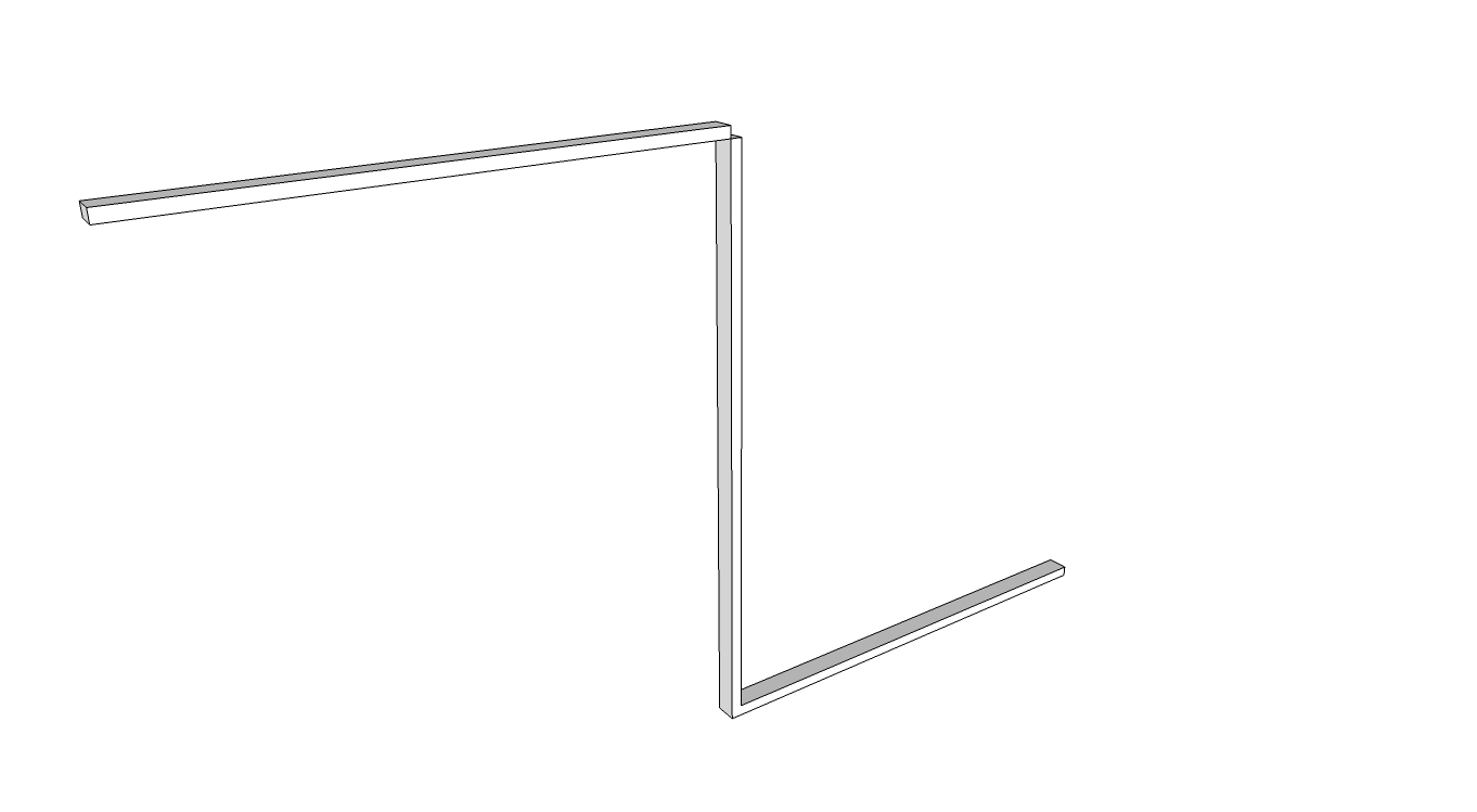
But the top plate is being drawn in the wrong/opposite direction to the bottom plate, even though the code is almost identical. See image below. Any ideas why? If I make the bottom plate and stud components as they're created, would that stop this behaviour?
-
That leads to my next stumbling block. I'm at a total loss on how to create a component from each element. I'm reading through the API and "Automatic Sketchup" PDF, but it still eludes me.
-
In future, instead of hard coding the dimensions, I'd obviously like to be able to select an edge or face, click my studwall icon, up pops a window where you can type in the relevant dimensions/properties etc, and it gets drawn as components (dynamic?) that can be edited later if needed. For now, how can I use a selected edge to use for the wall start and finish points?
-
Any other comments/tips/critique you can think of?
## draw a stud wall
# Basics first - bottom plate, studs, top plate
# later look into windows, jamb studs etc

# retrieve the current active model and selection
model = Sketchup.active_model
entities = model.entities
selection = model.selection

# wall overall length and height (outside faces of end studs, bottom of bottom
# plate to top of top plate)
## need to make this use the selection length
wallLength = 2000.mm
wallHeight = 2400.mm

# bottom plates
btmPlLength = wallLength
btmPlDepth = 45.mm
btmPlWidth = 90.mm
btmPlNo = 1

# top plate dimensions
topPlLength = wallLength
topPlDepth = 45.mm
topPlWidth = 90.mm
topPlNo = 1

# stud dimensions
studDepth = 90.mm
studWidth = 45.mm
studLength = wallHeight-(btmPlNo*btmPlDepth)-(topPlNo*topPlDepth)

# stud alignment
studOffset = 0.mm
studSpacingMax = 450.mm

# find the selected edge

# create bottom plate and make a component
btmPlCorners = []
btmPlCorners[0] = [0.mm,0.mm,0.mm]
btmPlCorners[1] = [0.mm,0.mm,btmPlDepth]
btmPlCorners[2] = [btmPlWidth,0.mm,btmPlDepth]
btmPlCorners[3] = [btmPlWidth,0.mm,0.mm]
btmPlSection = entities.add_face btmPlCorners
btmPlSection.pushpull wallLength

# create stud component
studCorners = []
studCorners[0] = [0.mm,0.mm,btmPlDepth*btmPlNo]
studCorners[1] = [0.mm,studWidth,btmPlDepth*btmPlNo]
studCorners[2] = [studDepth,studWidth,btmPlDepth*btmPlNo]
studCorners[3] = [studDepth,0.mm,btmPlDepth*btmPlNo]
studSection = entities.add_face studCorners
studSection.pushpull (wallHeight-btmPlDepth*btmPlNo-topPlDepth*topPlNo)

# copy array of studs

# create top plate face and push
topPlCorners = []
topPlCorners[0] = [0.mm,0.mm,wallHeight-topPlDepth*topPlNo]
topPlCorners[1] = [0.mm,0.mm,wallHeight-topPlDepth*topPlNo+topPlDepth]
topPlCorners[2] = [topPlWidth,0.mm,wallHeight-topPlDepth*topPlNo+topPlDepth]
topPlCorners[3] = [topPlWidth,0.mm,wallHeight-topPlDepth*topPlNo]
topPlSection = entities.add_face topPlCorners
topPlSection.pushpull wallLength
-
-
Just further to the above, thought I'd try to use selections to make components as you would with the mouse. For a single box (ie the bottom plate) there are 18 entities. I assume this is 12 edges and 6 faces. What's the easiest way to select all of those and make them a component?
And once that is a component and I add more entities (eg the stud), what's the best way to distinguish the new entities from the ones in that first component to make a new one?
Am I barking up the wrong tree here?
-
When a flat face is made on the ground 'manually' it always faces down, irrespective of the direction its edges were added to the model. However, when z!=0 the order of the creation of its edges affects a flat face.normal...
It's the same doing it in code.
If you make a flat face at z=0 it will always have face.normal as [0,0,-1].
The direction [clockwise/counter-clockwise] of the edges will affect the flat face-normal otherwise.When you pushpull in code the distance is always in the direction of the face.normal.
Using a -distance makes the extrusion in the other direction.
So what your code can do is check a flat face.normal and if face.normal.z<0 you know it's facing down or >0 it's facing up, or ==0 it's vertical... and you can adjust the distance to be +ve/-ve to suit...Incidentally another way to make rectangular timber plates, studs etc is to make a 1" cube component [defn], then add it using inst=entities.add_instance(defn, tr) where 'tr' is the point in 3d that it'll be inserted - tr=Geom::Transformation.new(point) - and then use another transformation ts=Geom::Transformation.scaling(point, x, y, z); inst.transform!(ts)
Where x/y/z are the three dimensions of the piece of timber.
That way you have a series of correctly sized pieces from the one original... -
Thanks TIG! That has certainly set me off on the right track. I like the unit cube idea. Have implemented that.
-
Still having some trouble, sorry. I have completely rearranged the way I started out to (try to) make use of classes, modules, methods etc. Seem to have gone backwards.
My intention is to have a 1x1x1 "unit_block" component, then when I want to draw a new piece of timber, do as TIG suggested and transform it accordingly. Timber is going to be a class and it will create the block of appropriately sized timber, then BottomPlate is a subclass of it and will also handle orientations and positions in the wall.
Here's where I'm at:
Class Timber

  # Timber properties;
  attr_accessor ;depth, ;width, ;length

  def initialize(depth, width, length)
    @depth = depth
    @width = width
    @length = length
  end # initialize

  def draw

    model = Sketchup.active_model
    ents = model.entities
    def_list = model.definitions

    unit_block = def_list.add "unit_block"
    unit_block.description = "This is a 1x1x1 block to use as a building block"
    def_ents = unit_block.entities
    base = def_ents.add_face [0,0,0], [0,1,0], [1,1,0], [1,0,0]
    base.reverse! if base.normal.z < 0
    base.pushpull 1

    inst = ents.add_instance unit_block, [0, 0, 0]

    ts = Geom;;Transformation.scaling(@depth,@width,@length)
    timber = inst.transform!(ts)

  end # draw

end # class Timber
I can't for the life of me see where this is wrong. I think I can't see the forest for the trees.
It's giving errors and not drawing an appropriately sized piece of timber when I call
t.new 1, 2, 3or
t.drawSorry for the noob questions.
-
The 'draw' method is special method used by the Tool class to draw temporary graphics - rubber-banding lines etc - it is automatically invoked if the script is launched as a tool - it expects 'view' as an argument - see the Tool class API...
You need to make your def called named perhaps 'make_cube()', not 'draw'.
It will do nothing unless you 'call' it withTimber.new(1,2,3).
So for example in the initialize() end the code withself.make_cube()Next...
Every time you run your [fixed] script in the same Model it will add a new cube component definition... incrementing its name from 'unit_block' to 'unit_block#1' etc, you probably don't want that.
So to make it once if it doesn't exist use...
unit_block=def_list.add("unit_block") unless unit_block=def_list["unit_block"]
This makes a reference to one if it exists, otherwise it adds it too...There are several ways of 'scaling' - see the Transformation API...
Your current transformation scales about [0,0,0] which might be what you expect, but you can also specify the anchor-point and limit scaling to certain axes etc... -
Thanks TIG. It works the first time I run it, but the second time I get the error:
%(#FF0000)[> sw = StudWall.new
Error: #<TypeError: /Library/Application Support/Google SketchUp 8/SketchUp/Plugins/set.rb:58:in `add_instance': reference to deleted ComponentDefinition>
/Library/Application Support/Google SketchUp 8/SketchUp/Plugins/set.rb:58
/Library/Application Support/Google SketchUp 8/SketchUp/Plugins/set.rb:58:in `initialize'
/Library/Application Support/Google SketchUp 8/SketchUp/Plugins/set.rb:102:in `new'
/Library/Application Support/Google SketchUp 8/SketchUp/Plugins/set.rb:102:in `initialize'
(eval):58:in `new'
(eval):58]class Timber # Timber properties; attr_accessor ;depth, ;width, ;length def initialize(depth, width, length) @depth = depth @width = width @length = length model = Sketchup.active_model ents = model.entities def_list = model.definitions unit_block = def_list.add "unit_block" unless \ unit_block = def_list["unit_block"] unit_block.description = "This is a 1x1x1 block to use as a building block" def_ents = unit_block.entities base = def_ents.add_face [0,0,0], [0,1,0], [1,1,0], [1,0,0] base.reverse! if base.normal.z < 0 base.pushpull 1 inst = ents.add_instance unit_block, [0, 0, 0] ts = Geom;;Transformation.scaling(@length,@width,@depth) block = inst.transform!(ts) end # initialize end # class Timber class StudWall def initialize # input the wall dimensions prompts = [ "Wall Height", "Wall Length", \ "Btm Pl Depth", "Btm Pl Width", \ "Stud Depth", "Stud Width", "Stud Max Spacing", \ "Top Pl Depth", "Top Pl Width" \ ] defaults = [ "2400", "1000", \ "45", "90", \ "90", "45", "600", \ "45", "90" \ ] results = inputbox prompts, defaults, "Stud Wall Properties" # assign the input to variables wH = results[0].to_f.mm; wL = results[1].to_f.mm bPD = results[2].to_f.mm; bPW = results[3].to_f.mm sD = results[4].to_f.mm; sW = results[5].to_f.mm sMxSp = results[6].to_f.mm tPD = results[6].to_f.mm; tPW = results[7].to_f.mm bPL = wL; tPL = wL bPNo = 1; tPNo = 1 sL = wH-(bPNo*bPD)-(tPNo*tPD) # create bottom plate btmPl = Timber.new (bPD,bPW,bPL) # create single stud # pt = Geom;;Point3d.new 0,0,bPD # tr = Geom;;Transformation.new pt # ts = Geom;;Transformation.scaling(pt,sD,sW,sL) # stud = Timber.new (sD,sW,sL) # duplicate studs # insert nogging # create top plate # pt = Geom;;Point3d.new 0,0,bPD+sL # duplicate studs # insert nogging # create top plate # pt = Geom;;Point3d.new 0,0,bPD+sL # tr = Geom;;Transformation.new pt # ts = Geom;;Transformation.scaling(pt,tPW,tPL,tPD) # tP = entities.add_instance unit_cube, tr # tP.transform!(ts) end # initialize end # class StudWall -
Getting there...
When you make a new definition add geometry to it immediately.
Empty definitions/groups don't survive in code...Try something like:
unless unit_block=def_list["unit_block"]
  unit_block=def_list.add("unit_block")
  ### add geometry to unit_block.entities
  ### add description to unit_block.description
  ### etc
end
### now add instance, knowing the definition exists and has geometry
which might be clearer?
You don't need to add geometry to the component if it already exists !Another tip - use
Timber.new(bPD,bPW,bPL)
not
Timber.new (bPD,bPW,bPL)
don't leaves a space in front of the arguments' ()
Hello! It looks like you're interested in this conversation, but you don't have an account yet.
Getting fed up of having to scroll through the same posts each visit? When you register for an account, you'll always come back to exactly where you were before, and choose to be notified of new replies (either via email, or push notification). You'll also be able to save bookmarks and upvote posts to show your appreciation to other community members.
With your input, this post could be even better 💗
Register Login


Advertisement