From SketchUp to Reality
-
Coming along nicely Dale

As regards disabled access goes over here, we have to provide quite a number of considerations as standard. While these items may not make a lot of sense to able body house holders, I remind them that they may appreciate the extra access provisions in time AND that some day they may grow old and be glad of them
-
Some of those ideas just make sense even for the able bodied. Wider doors and straight runs into rooms make sense for moving furniture around. I've been in some newer homes that look great but you can't move a couch or a bed in without damaging the walls. What kind of sense does that make? The house we had designed a few years ago (but have yet to build) was, at our request, designed with 36" wide doors and other features that would make the house accessible to wheelchair users but it was more to make the house easier to live in for anyone.
-
Just wondering how progress in going?

-
Mike, I apologize for the delay in updates, but it has been dawn to dusk, then fall into bed hectic around here for the past month.
Just a couple more days of madness, and I will do a big update.
Winter strikes hard and fast here, and I am really pushing to not get caught.
Thanks so much for your interest. -
@dale said:
Mike, I apologize for the delay in updates, but it has been dawn to dusk, then fall into bed hectic around here for the past month.
Just a couple more days of madness, and I will do a big update.
Winter strikes hard and fast here, and I am really pushing to not get caught.
Thanks so much for your interest.Well that's plenty of an update. How blessed to be thus engaged. Looking forward to hearing the details.
-
The past month has been so hectic, that as I noted previously, I just haven't had the time for proper posting.
Aside from managing to get my fascia and roof on, I have been acting as the gopher for the stone mason.
Introducing, "he who cannot be named" himself, in "The Chronicles of a full masonry fireplace".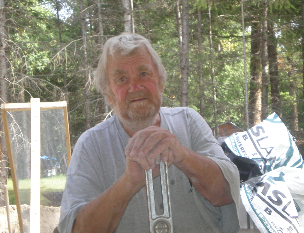
Don't let those sad eyes fool you, this 73 year old German trained mason is a taskmaster, but master is the operative part of this statement as well.
This is the 3rd fireplace he has built for us, and if you have ever had one, they are hard to live without. In the end the 40,000 lb (18,200 kg) monster will keep the entire house warm in the case of power failures.
But it has to start somewhere: Judy shoveling in one of the 15 or so truckloads of sand.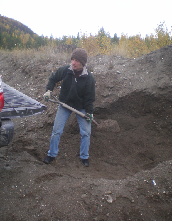
Starting at the base of the rough in, and following through with the Hearth, which cantilevers into the building.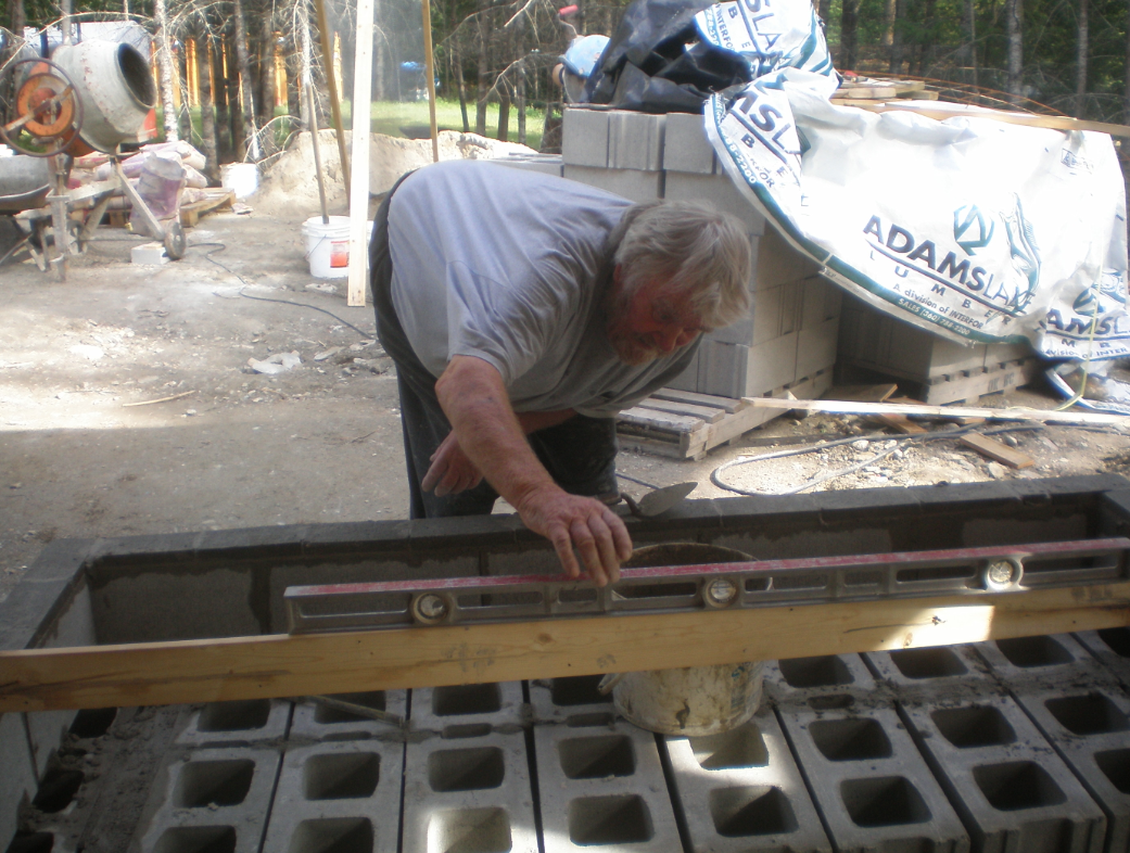
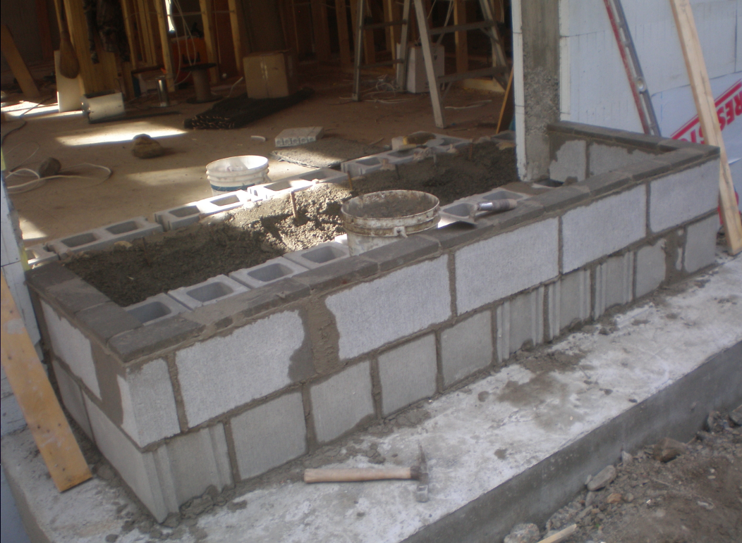
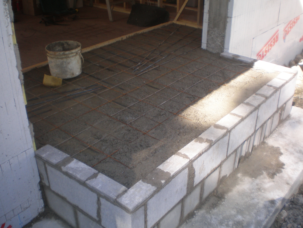
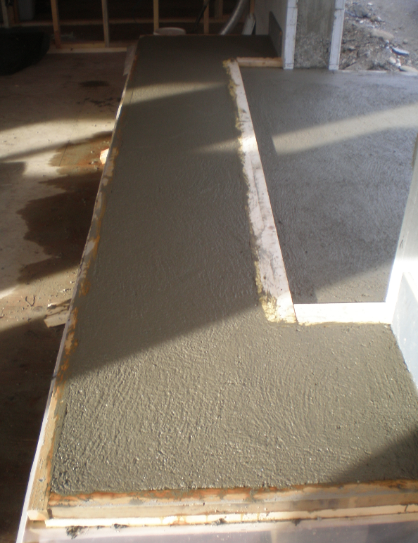
-
Continuing on to the fire box, which, if you are familiar with fireplaces, is similar to a Rumford with it's sloping back and sides, but much deeper. This is done to make the smoke shelf more effective. In the real world it means the front of the fireplace doesn't get blackened, as it virtually never smokes unless there is extreme downdraft conditions.
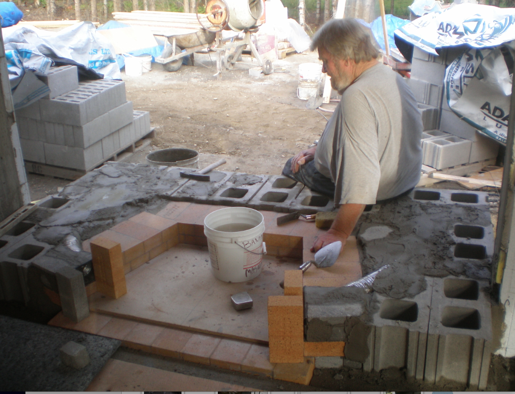
Notice the firebricks are set with there 9" depth perpendicular to the fire box. It takes more firebricks this way, but is less likely to crack, and way more efficient at maintaining heat.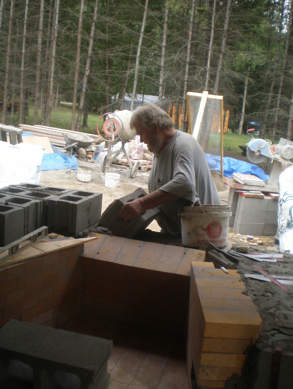
Apologies over the quality of some photos, as they were quick iphone shots.
Next is the firebox with the steel damper in place.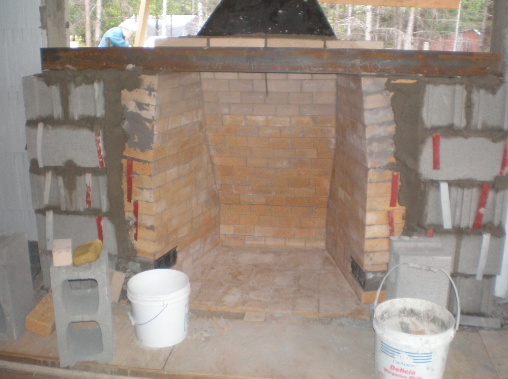
Interior rough in complete.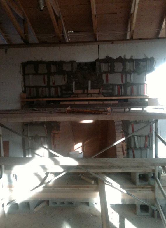
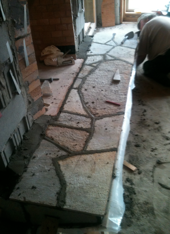
Then it was putting the flagstone onto the hearth. The hearth is about 18"(45 cm) off the floor. This is so when you sit in front of the fire, you are looking right at it, and the heat is reflecting off those sloped sides and back, right at your body.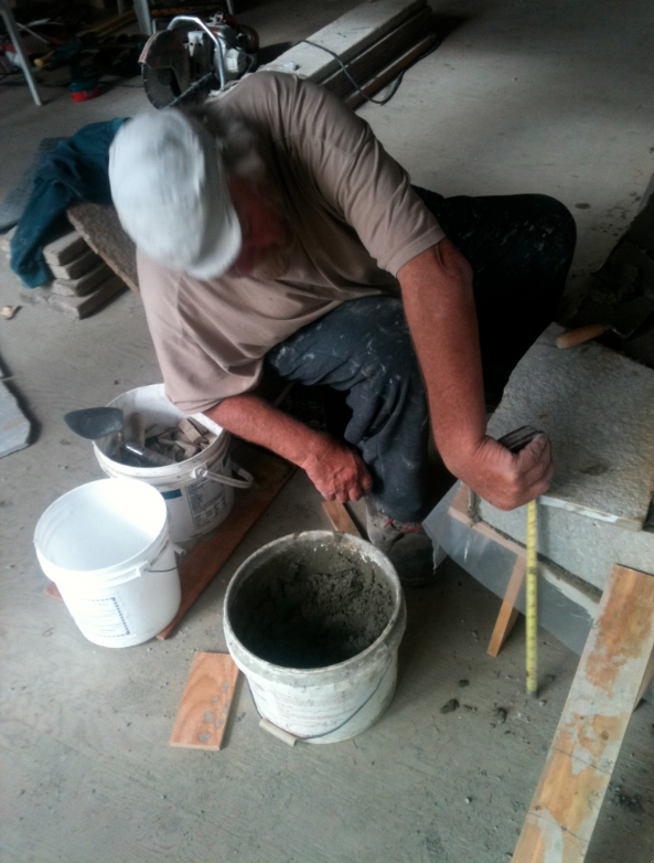
-
With the weather holding, we moved outside to take advantage of this.
Chimney flue through the roof.
He angles the first part of his flues, as he says it causes the smoke to be pulled faster up the chimney.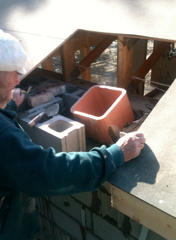 and reaching above the roof.
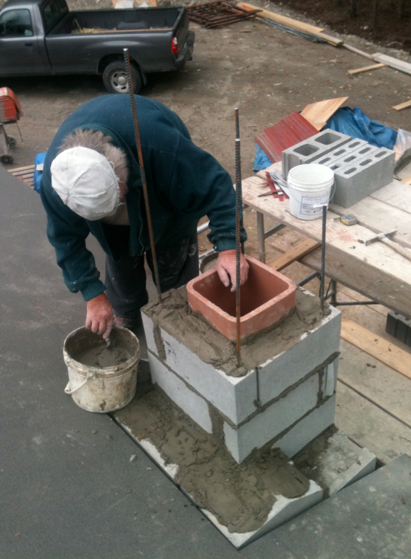
To be continued.
Cheers
Dale -
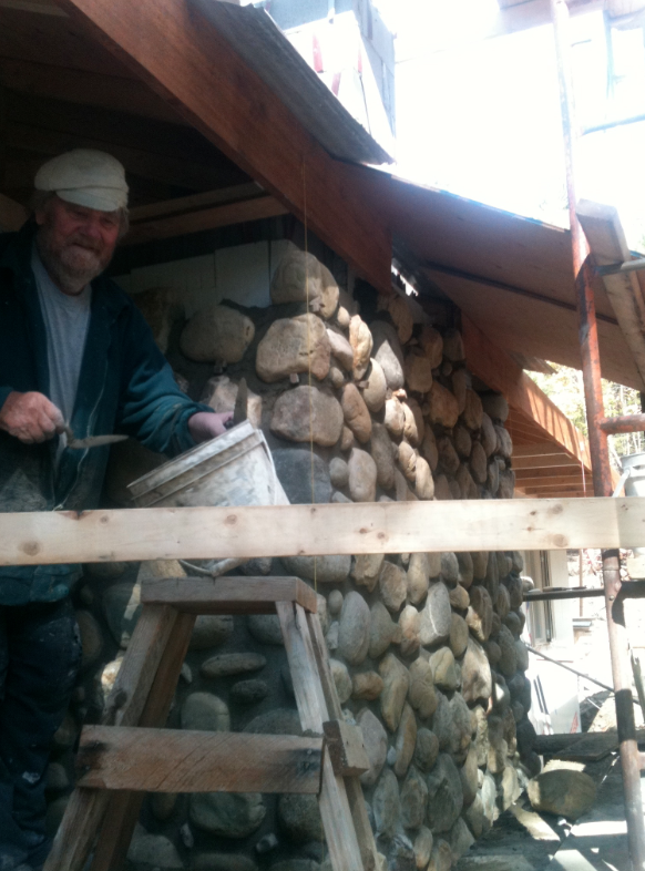
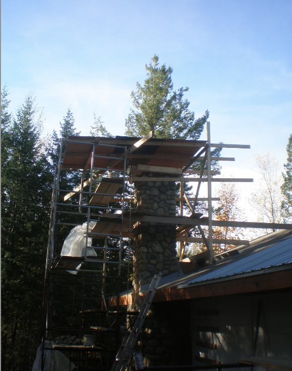
Next we started the actual stone work with river stone that we had gathered.
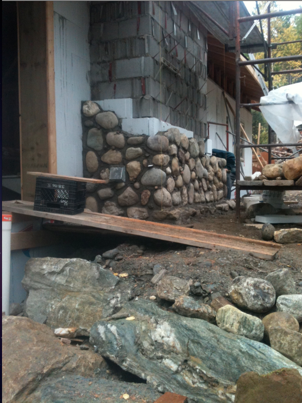
And continued to the soffit.[attachment=3:2ipzng5w]<!-- ia3 -->ExTerior stone to soffit.png<!-- ia3 -->[/attachment:2ipzng5w]
Stone above roof.[attachment=1:2ipzng5w]<!-- ia1 -->Screen shot 2011-10-16 at 7.36.11 AM.png<!-- ia1 -->[/attachment:2ipzng5w][attachment=2:2ipzng5w]<!-- ia2 -->stone above roof.png<!-- ia2 -->[/attachment:2ipzng5w]
And pouring the cap.[attachment=0:2ipzng5w]<!-- ia0 -->Screen shot 2011-10-16 at 7.38.12 AM.png<!-- ia0 -->[/attachment:2ipzng5w]
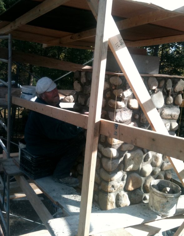
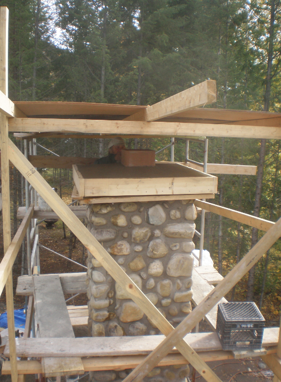
-
Then the interior stone work. This shows the arch form with beginning of stone placement for the arch.
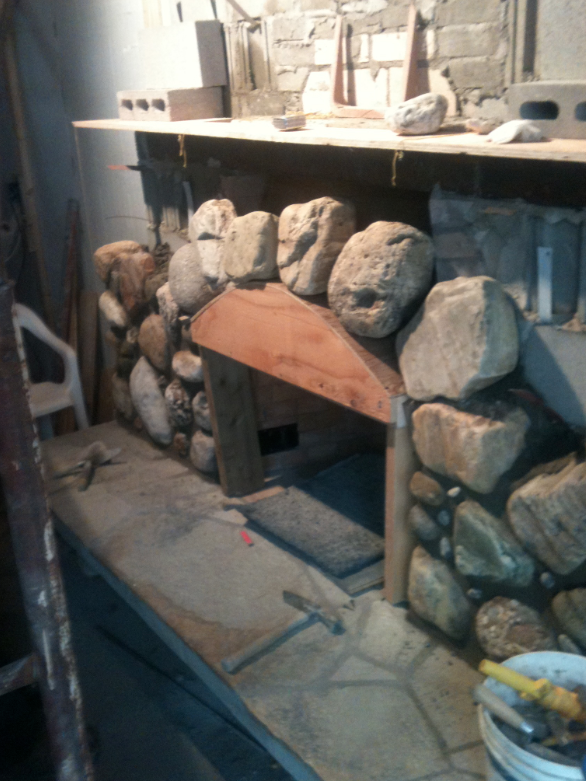
I laminated 4" Douglas fir for the mantle.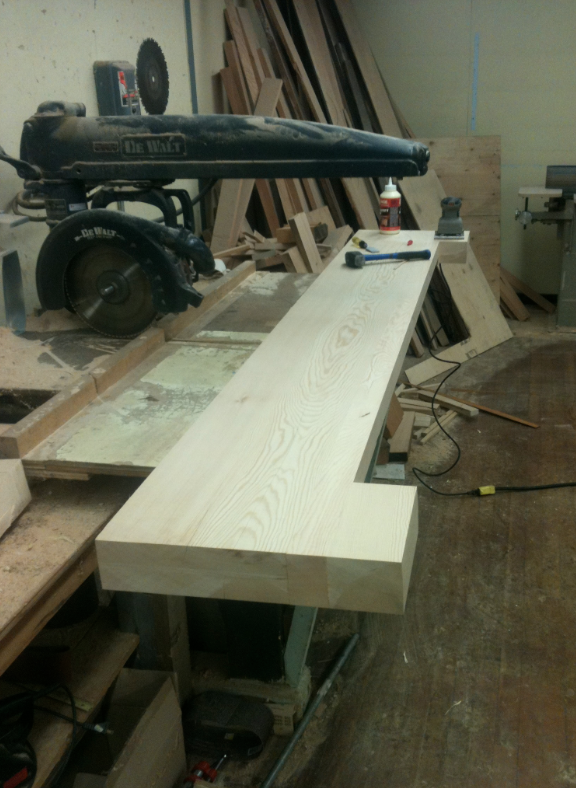
A shot showing the quarter sawn grain of the Fir.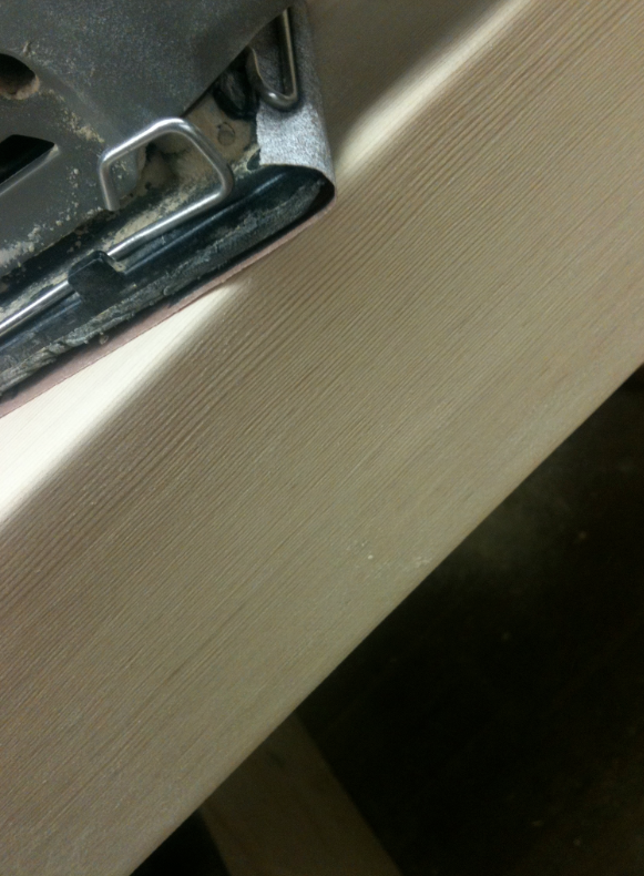
Mounting the mantle.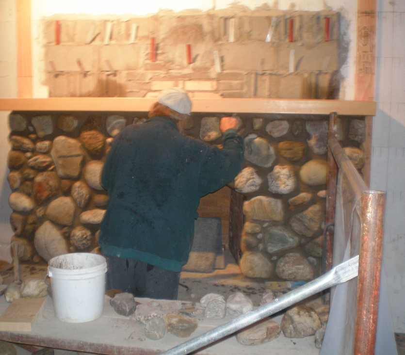
-
German trained mason, a taskmaster,...
...73 year old
you will be fine inside your home in those stormy and cold days Dale
-
 WOW
WOWGot to say this is really impressive !! I love how clean the work is ! Good luck with finishing it and living in it!
How are the outer rocks of the chimney held in place ? I have the impression they are not only held by concrete .
Cheers!
-
where is the stonehenge? I don't know, but I know that somebody can create a lot of beautiful things with stones.
keep up dale thumb up .
. -
Juan, Elisel, Jaryn
Thanks for the encouragement.
Amongst the moments of excitement, there are moments when I question my sanity.
But on a piece like this, there is so much personal involvement when you have shovelled the sand and collected the stone, everything has a story.
Anyway, for the final on the fireplace, the exterior stone completed.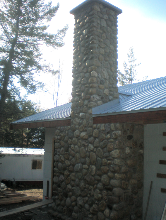
And the first fire, a tribute to the mason and accompanied with a nice glass of red wine.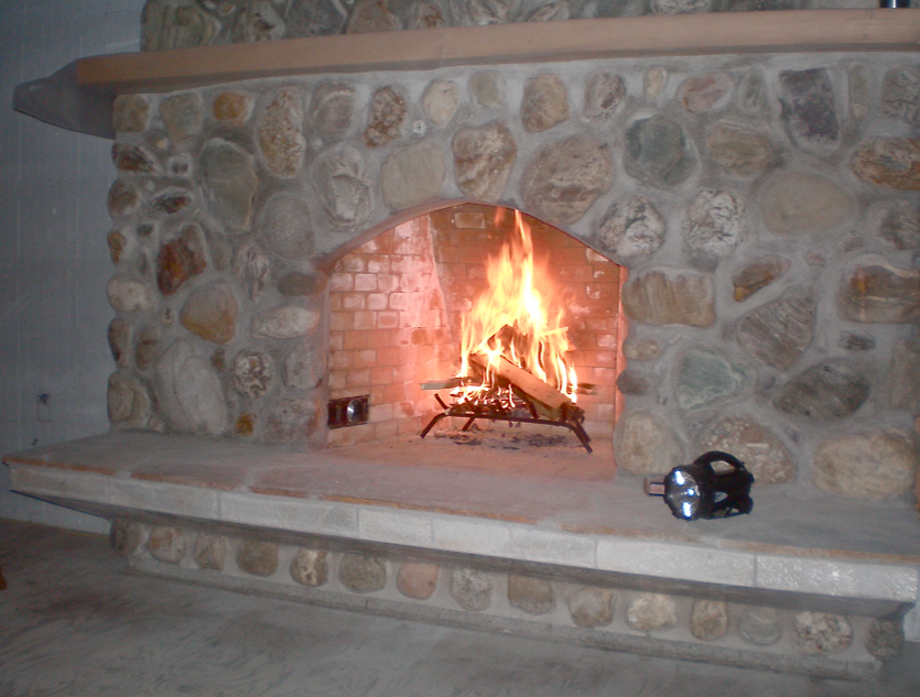
-
In Finland, it has also been customary to have a little "first fire" celebration. Traditionally all the smoke from the fireplace comes in until the master mason has been given his vodka. Then he goes up on the roof and drops a little stone in the chimney to break the thin glass he has placed there.
Good luck to your project
Anssi
-
Anssi
Our mason told us this exact ritual, although apparently the schnapps in Germany had to be accompanied by the monies owing, or the glass remained. -
We got a spell of great weather at the end of the fireplace construction, so we managed to get the steel roofing on as well.
Unloading the pallets.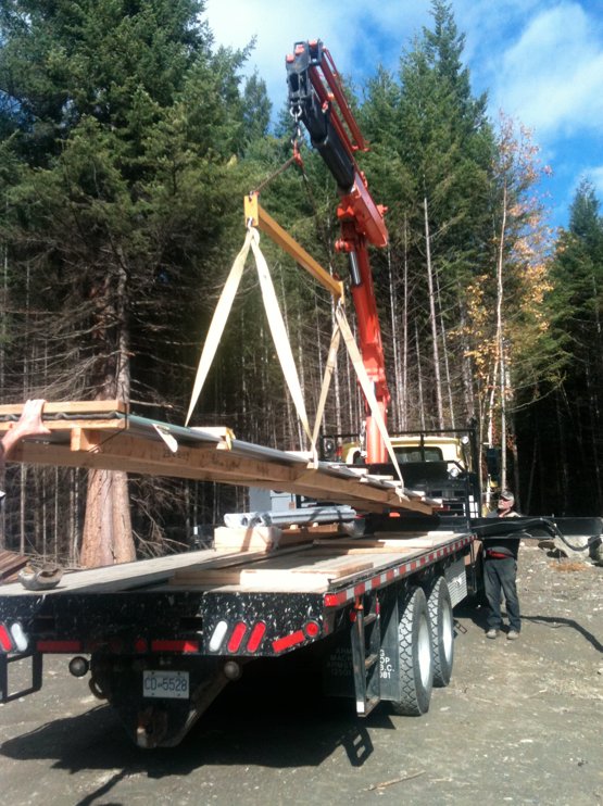
Flashing detail.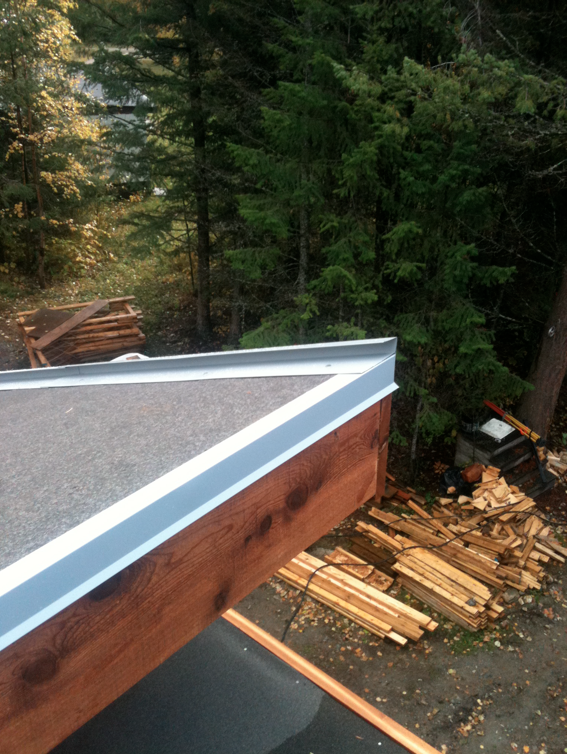
Laying the steel.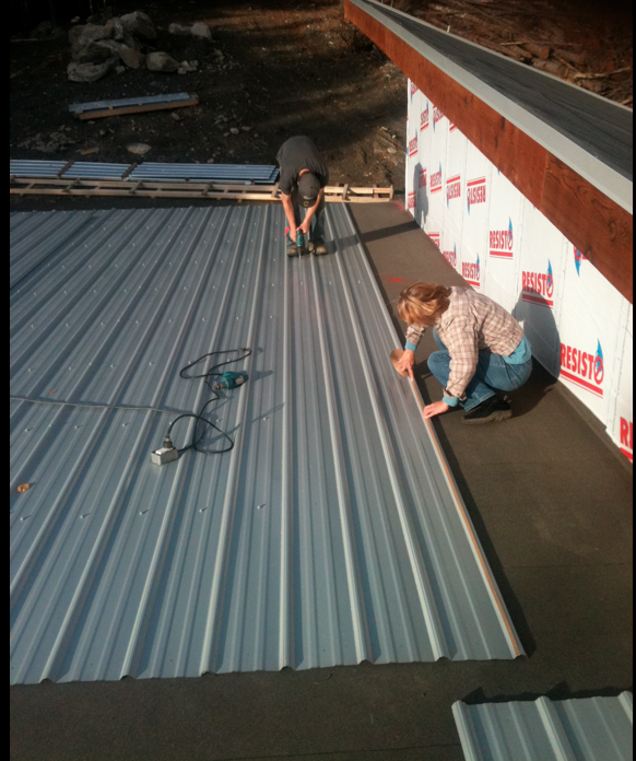
-
Yesterday was a big day, as with the main floor hydronic pipes in place we poured the upper floor.
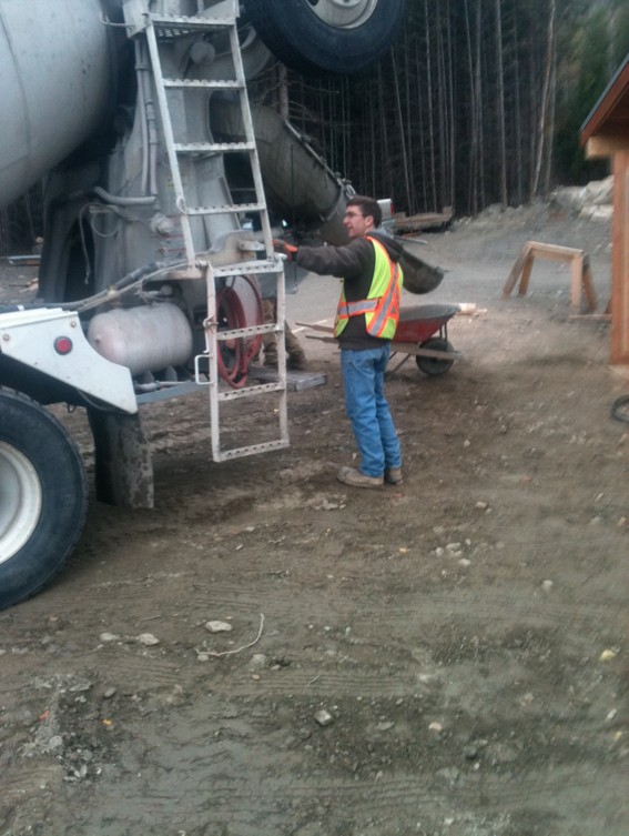
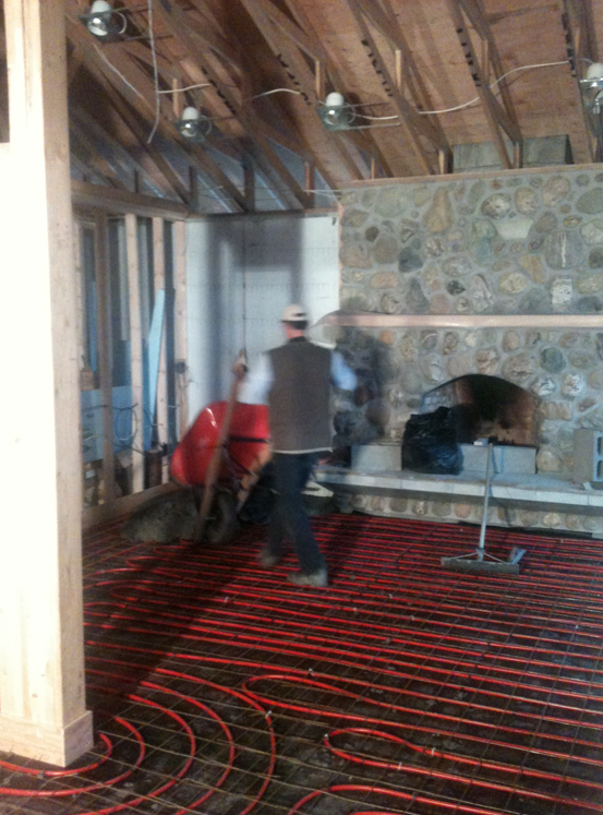
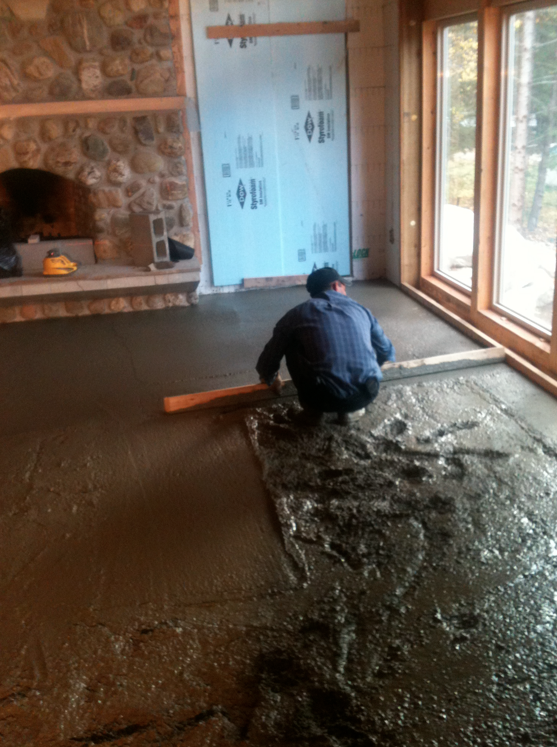
-
This house has had its share of wildlife incidents.
On the way back from picking up our plumbing fixtures we saw this wolf on the highway.
Maybe these are good omens.


-
We did a gridwork of 2'x2' cuts with a diamond saw in the concrete floor,
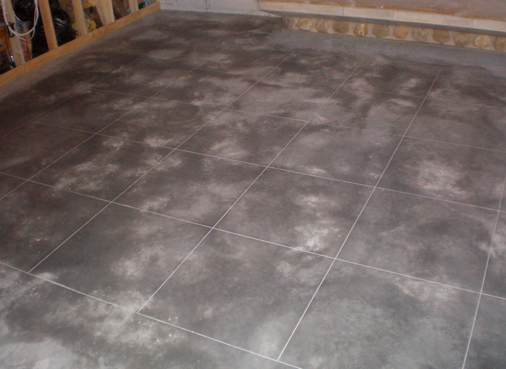
And then applied a Padre brown Scofield acid stain yesterday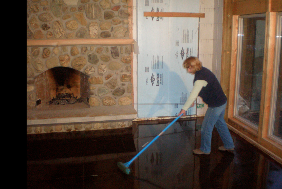
And washed it down last evening.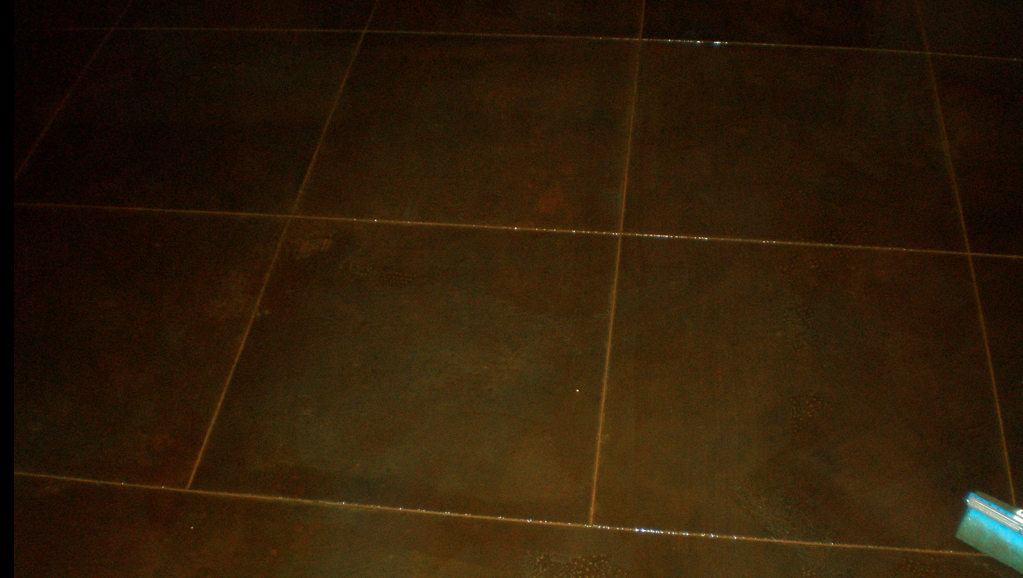
The recommendation is to let the concrete cur for at least 14 days, but I have found you get a deeper richer color if you stain quite quickly after placement.
The color doesn't really show its potential until the clear finish is applied, and I am waiting until I can warm the floor with the hydronics before I do that, which should be complete today.
Cheers!
Advertisement


