Help Needed Intersecting a Stile and Rail
-
There should never be a reason to explode a component to edit it.
I can think of several easier ways to do this.
One way would be to:
Open the stile component for editing.
Select the faces that make up the inner edge profile.
Copy them (Ctrl+C).
Close the stile component.
Open the rail component for editing.
Go to the Edit menu and choose Paste in place.
Select all of the geometry for the edge profile and the rail.
Right click on the selection.
Choose Intersect Faces>With Selected.
Delete the waste
Correct the face orientation in the cope.
Repeat for the opposite end.Or easier for the second end, I would make the rail half as long as needed, cut the cope on the first end, select all the geometry in the rail component, Move/Copy the selection over to the side where the missing half of the rail is supposed to be, flip the copy and join it to the original copy. Delete the coplanar edges and you're finished.
Another way would be to copy (Ctrl+C) the end of the stile, open the rail for editing, Use Edit>Paste in place to paste the end profile of the stile into the rail component, Use Ctrl+Push/Pull which will allow you to push the profile through the rail and a little beyond, similar to what I had done in the SKP I posted. Select all of it, run the Intersect and delete the waste. Correct the face orientation.
Probably the easiest if you have SU8 Pro is to use the Intersect option of the Solid Tools.
None of these involve exploding components which you shouldn't need to do.
-
@daves said:
Ed,
I followed your tutorial and all went well. I do not understand why you have to explode the components before editing, but I guess that is one of the mysteries of life.
Now, if I can be so bold, a follow up question. Is there a quick way to repeat the profile on the other end of the rail? Or, do I have to do the procedure for each side?
Thanks again.
Dave
DaveR is completely right,it's just that for me it was easier to temporary explode the components to make the final ones.

-
I just realized that I was replying to people incorrectly. I did not read the name of the person closely and thus addressed my replies to the wrong person. So .... Thanks to ALL who helped me resolve this issue. This is a GREAT resource and has some great people involved with it.
Dave
-
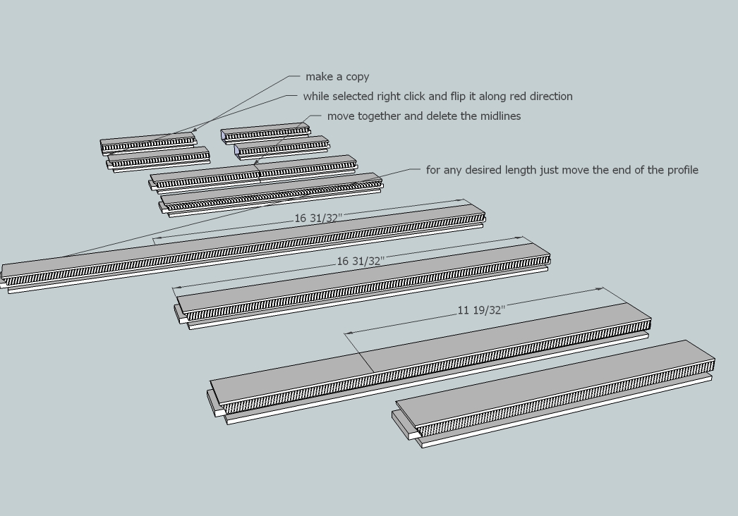
Good illustration there, Elisei. Once you've drawn a rail (and a stile) with this cope and stick profile, you should never need to draw another one. You only need to modify the length of the first one. You can also change the overall width of the frame members so you'll have every size covered.
-
OK, let me show my ignorance one more time. How do you recommend changing the length? If you use the Scale Tool won't that change the size of the profile on the end of the rail? And, the Push-Pull Tool can't be used because neither end is flat?
DaveS
-
-
@daves said:
OK, let me show my ignorance one more time. How do you recommend changing the length? If you use the Scale Tool won't that change the size of the profile on the end of the rail? And, the Push-Pull Tool can't be used because neither end is flat?
DaveSModify your 'View'. Select ALL of the 'end' geometry by left-right fence and Move it!
[use axis-lock (shift) if required...] -
As I said in my last image...select the entire end of the profile and move it to the desired length .
-
You can use Fredo Scale if you want but I would just drag a left to right selection box around the end that needs adjusting and use the Move tool. To see that in action, take a look at the video at this link.
-
Three of us with the same answer. Must mean something.

-
Got it!
I must learn to read CAREFULLY. You said select the end and move. I didn't know you could do that. I was trying to select the end of the component and that obviously won't work. You folks (all of you) are very helpful. I learned a lot today.
Thanks.
DaveS
Hello! It looks like you're interested in this conversation, but you don't have an account yet.
Getting fed up of having to scroll through the same posts each visit? When you register for an account, you'll always come back to exactly where you were before, and choose to be notified of new replies (either via email, or push notification). You'll also be able to save bookmarks and upvote posts to show your appreciation to other community members.
With your input, this post could be even better 💗
Register Login


Advertisement