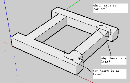
How to avoid generating line between joint?
-
drawing attached to show where is the line
-
Hi Tig,
Thanks for your suggestion. I am trying to understand all of that. I updated the program to draw the rungs in non- coplanar way. For this, I need to pushpull them seperately.
Regards,
Cean
Hi Andrew,
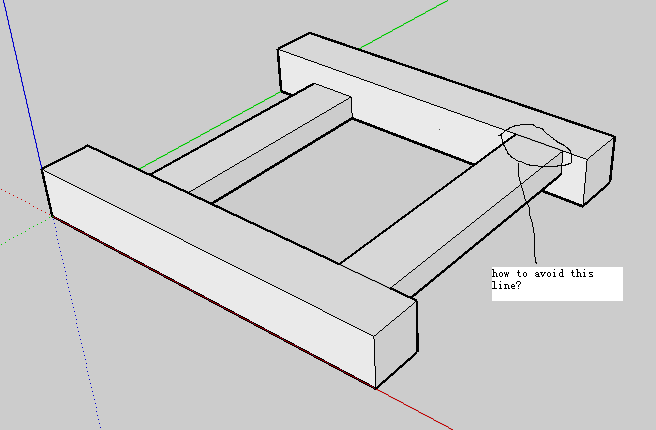
The real model I want is far more complicate than I showed here. There are much more unwanted lines like this. It's difficult to delete them all by hand and do it repeatly when I changed a parameter.
Thanks
-
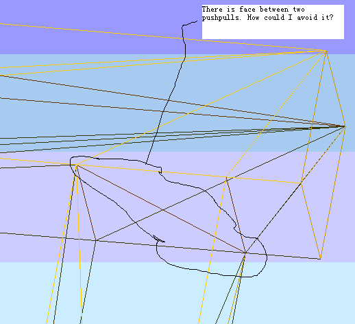
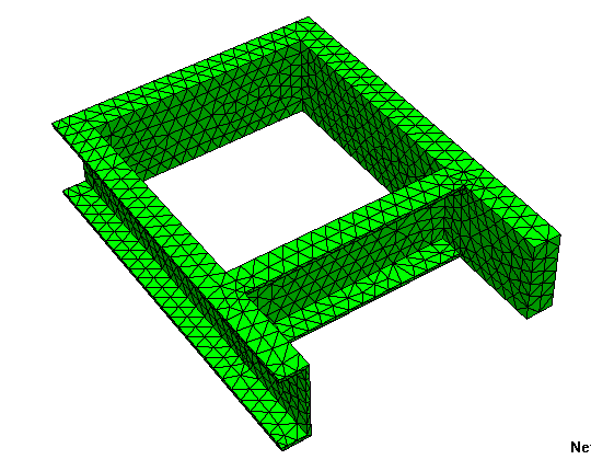
The problem for that line is when I output a STL file, it generates a plane inside the geometry and stop me meshing for FEA simulation.
The photo showed here is after output STL file and viewed under GMSH.
-
Hi Andrew,
Tried the 'enable length snapping", seems no improvement.
The rung is assumed to be drawn on the surface of the left bar and end on the surface of right bar. But the two joints are shown in two different ways at two ends.
I was wondering if there is a 'Union' command I could use? Or the 'snapping' should look after this.
Regards,
Cean
-
The easiest way to draw the ladder is using pushpull, but a side-effect is you having some lines you don't want. About the only alternative is to draw the shape using a mesh.
It might be easier to erase the lines afterward, rather than try to avoid drawing them in the first place.
Thom's excellent cleanup script might be of interest, however it won't delete the edges until the internal face has been removed.
-
As I said before...
Work inside a group.
Draw all of the faces at z=0...
Erase all edges with 2 faces [coplanar].
PushPull the one remaining face up as needed...
Result = 3D ladder with NO inner faces or stray edges...
-
Hi Tig,
As shown in my second photo, I made the rungs irregular in height. And I want the side bar and rungs made of PFC channel in real. So I have to extrude the side bar and rung in different direction seperately.
Regards,
Cean
-
No you don't !

First make a single 'ladder' face as I explained before... and extrude it up the maximum height.
Now add edges to form the rungs over the face at this topmost height, and PushPull the newly split off rung-face down to suit - at this point you won't get the internal faces problems - but you will get some coplanar edges formed on the sides where the rung is lowered... but when you are done you can test thegroup.entities.to_afor any edges that haveedge.faces[1]- they all should - AND those whose faces are coplanar -edge.faces[0].normal==edge.faces[1].normaland.erase!them... You can of course add edges on the bottom face of the 'ladder' and PushPull those rungs up too, so that they then have no faces coplanar with the side members........
This is somewhat simplified outline, but it should give you the idea. -
I am trying to carve the ladder out from a big cube.
New code, new approch and new problem.
-
Should work
@entities.to_a.each{|e|e.erase! if e.valid? and e.class==Sketchup::Edge and edge.faces[1] and edge.faces[0].normal==edge.faces[1].normal}
No need to==truethough.
but I notice you have some reversed faces so add a test like@entities.to_a.each{|e| e.erase! if e.valid? and e.class==Sketchup::Edge and edge.faces[1] and (edge.faces[0].normal==edge.faces[1].normal or edge.faces[0].normal.reverse==edge.faces[1].normal) }
What errors do you get ? -
the PFC channel is not out.
Not understand all this code below. Must be something wrong.
@entities.to_a.each{|e|e.erase! if e.valid? and e.class==Sketchup;;Edge and edge.faces[1]==true and edge.faces[0].normal==edge.faces[1].normal}
-
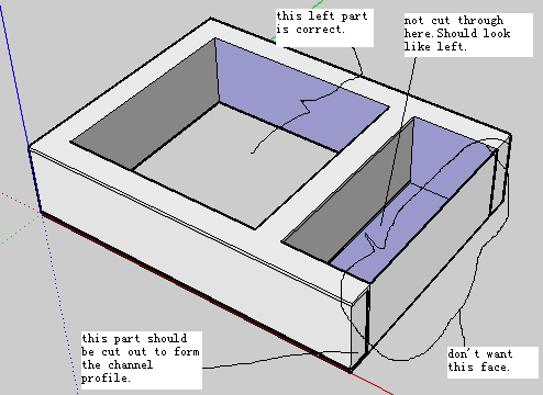
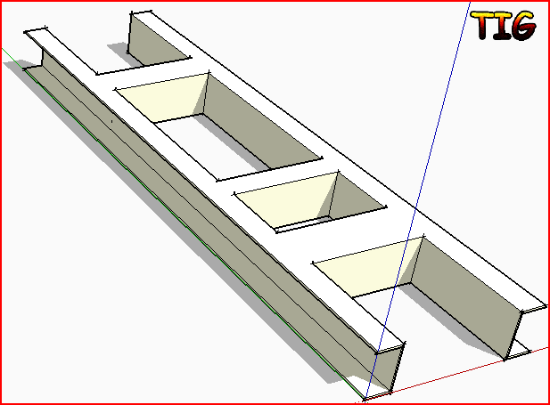
Now the problem is un-wanted face. I added labels on the photo.
-
In order of your added notes...
The part that is 'OK' has at least one face reversed the wrong way [blue] ?
The part that isn't 'cutting though' - is the pushpull distance the same and the 'ctrl' key option set 'false' ? Also is the face you are pushpulling oriented the same way as the other one ?
The thin end wall seems to arise because the pushpulled face is not exactly the same size and the hole you desire - so a thin 'rung' remains.
To make the PFA profile... once all if the ladder's form is done you draw the profile of the desired 'hole' on the end face and pushpull it along the whole length until what's left is the PFA ???
This should all be relatively straightforward.
Make it manually and then replicate the steps in your code - it's quite easy
-
Hooray! I knew you could do it !

-
Hi TIG,
Finally made it and got my mesh.
To cut through, need to cut from the opposite direction.
To cut in (make a shell), need to cut from outside to inside.No need to do all the |e|e.erase! ... check.
Thanks
Hello! It looks like you're interested in this conversation, but you don't have an account yet.
Getting fed up of having to scroll through the same posts each visit? When you register for an account, you'll always come back to exactly where you were before, and choose to be notified of new replies (either via email, or push notification). You'll also be able to save bookmarks and upvote posts to show your appreciation to other community members.
With your input, this post could be even better 💗
Register Login


Advertisement