Help Me Draw A Dome [TUTORIAL]
-
Hi Gaieus
I’ve managed to enable the Scale text box to allow me to input a scale of 1:1 but still something doesn’t seem right.
When I click print preview and then page through the pages and when I come back to my first page, my model disappears. I have to exit the preview and redo the print preview. Anyways that may be a bug in SU and not a real train smash to keep going back and forth.
Going forward is where I'm really having some issues. I’ve attached a PDF of my model to scale but every time I change my scale to 1:1, my page size increases by almost double and then when I change it back to the size of which an A3 page should be, my scale goes to, for e.g 1:1.5
I then measured my model to see if logically, it can fit onto an A3 page and I found it wont fit on 1 page but by overlapping it onto 2, it will fit perfectly, which is fine as I can match the 2 after printing almost like a puzzle but I cant seem to get my model to evenly spread over 2 pages. The brown dome for e.g is 12” (Width) X 13” (Height). An A3 page is 11.69” (Width) X 16.54 (Height).Can we evenly spread both domes across 2 pages? The first half will be on the first page and preferably centered and not too much towards the edge as this can be a problem because my printer doesn’t print right at the end so we need to leave a slight margin. Same with the second half. It needs to be a little away from the edge.
Really appreciate your assistance.Thanks
Regards
D0me
-
No Dome,
It seems that your whole dome would not fit only on an A1 paper in scale 1:1. I happen to have LayOut, too, where it is much easier to place a SU model into paper space, align it and whatnot but even when I tried to put the model on an A2 landscape paper (like two A3 portrait side by side), it only fit at 1:2.
Why exactly do you need it 1:1?
-
Hi Gaieus
@gaieus said:
No Dome,
It seems that your whole dome would not fit only on an A1 paper in scale 1:1.
Would only part of the model, that is 1 quarter (slice) of my dome, namely the Sand and Refractory dome as described in my previous post fit onto an A1 page?
@gaieus said:
I happen to have LayOut, too, where it is much easier to place a SU model into paper space, align it and whatnot but even when I tried to put the model on an A2 landscape paper (like two A3 portrait side by side), it only fit at 1:2.
So we'll probably need 4 X A3 portrait Side by Side to fit it to a 1:1 scale? If so and can be done that way, it will just make my task of putting a puzzle together a little more tedious but possible which I am fine with.
@gaieus said:
Why exactly do you need it 1:1?
The reason for a 1:1 scale is because once printed, I can use it as is to trace out the lines of my dome straight onto wood to make my Curved Wood Spinner as well as other guides to help build the dome and from the section cuts you helped me create, I get all the info I need to make my task of building the dome easier.
However since this is the first time I am doing a sketch (not 1 of my forte's actually until you made the tutorial so exciting and vibrant that I couldn't resist but go further and further), I may be taking this approcach the wrong way and if so, please can you advise me how to do this the right way for example print my model to A3 on a scale that's maybe 1:4 and then sketch it out manually on a larger suface that can accomodate such a large drawing or whatever other ideas and advice you have?Thanks
Regards
D0me -
OK, I see the reason for the 1:1. I'll see what can be fit on what kind of paper. The problem with the straight SU output is that you can never set the tiling normally and SU tends to print the model all over a whole chapter of papers.
-
OR
Draw a grid over the section cuts on a new layer and print out 1:4. Make sure one grid line intersects an end. Draw the same grid on plywood 4x larger. Mark the gridlines where the top, midpoint and bottom of each arc intersect and put in small nails. Then just like you draw an arc in SU put a 3mm piece of plywood about 80mm wide and sufficiently long on edge and bend it until it rests on the three nails. Mark the curve with a pencil. Double check (chippie's rule: measure twice cut once). Cut with jigsaw.
-
OR
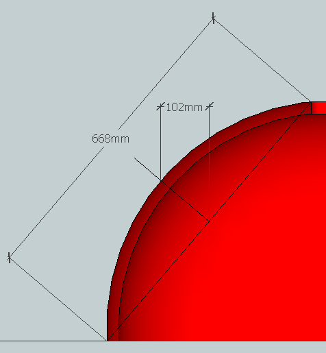
More simply get SU to give you the dimensions of the chord and the distance between the mid points of the chord and the arc and mark those on the plywood. Use the plywood rule as above.
Sorry bit sleepy talking about a grid!
-
@gaieus said:
OK, I see the reason for the 1:1. I'll see what can be fit on what kind of paper. The problem with the straight SU output is that you can never set the tiling normally and SU tends to print the model all over a whole chapter of papers.
Thanks Gaieus
I'll wait for you to come up with a solution.Chris, I'm reading through your post, trying to understand what was said. I find it a little bit confusing but I'm sure after reading it a few times, ill make sense of what's said.
Thanks guys
Regards
D0me -
-
Hi Guys
@chrisglasier said:
OR
More simply get SU to give you the dimensions of the chord and the distance between the mid points of the chord and the arc and mark those on the plywood. Use the plywood rule as above.
Sorry bit sleepy talking about a grid!
Thanks for the image which further clarifies your explanation. I now understand it much better and I am now on the same "Wave Length" as you. I will give your advice a try. Just 1 question. Since I don't have any plywood lying around, what else can I use to bend around the nails to create the curve?
As a tripple check, once Gaieus finds a solution to print the model Spanned accross multiple A3/A2 pages, I can place each curve over the ones I draw manually. This way, I can use chippies rule improvised a bit, Measure Thrice, cut once.
Thanks
Regards
D0me -
One problem with the A3/A2 pages in LO that you cannot spread a model through them in 1:1 tiling. So if I use LO, I cannot use 1:1 but if I use straight SU output (for tiling the object), I cannot control tiling and SU will tile the model through an unnecessarily large number of papers.
-
Go mad and buy yourself a sheet of 3mm plywood. It is always useful for protection if nothing else. It is important to let the plywood make an even curve so you should push the mid point with your non drawing hand rather than "bending" it. The same really but I think you understand the intention. Also that is why metal would not be so good, as it will take up some of the curve and not be absolutely true for re-use.
When you are ready can I suggest you revert to the reality thread? I think some members would be interested in seeing this project finally coming to fruition. That would let them know.
Btw multiple A3/A2 pages is not very environmentally friendly!
Good luck
-
Hi
@gaieus said:
One problem with the A3/A2 pages in LO that you cannot spread a model through them in 1:1 tiling. So if I use LO, I cannot use 1:1 but if I use straight SU output (for tiling the object), I cannot control tiling and SU will tile the model through an unnecessarily large number of papers.
If we print the model to a PDF file in A1 format, will we get it on a 1:1 scale and if Yes, is there 3rd party software to break apart the A1 model in to multiple A3 pages.
If not, are there any aternatives you can think of.
1 idea comes to mind. Is it possible to print my model to 1:1 scale in a JPEG image format?
The reason I ask is because maybe I can print it to a JPEG format and then crop out sections of the arc one at a time. The cropped size will be just enough to fit an A3 page. With a little bit of effort and a steady hand, I should be able to cut apart the entire arc and fit it onto multiple A3 pages. This is just a thought. I don't even know if it will work or even make much sense.Thanks
Regards
D0me -
I tried to "print" it tiled from SU into pdf but in vain - most of the lines just did not show up.
Here is a pdf file printed the whole structure on an A0 page at scale 1:1. Maybe a Mac user could also export it as 1:1 pdf straight from SU either tiled on A3 or on an A0 paper (this is not possible from Windows).
I have also exported a png file at "1:1" but raster image files do not really have "physical sizes" - it all depends on the conversion between digital and physical through a value printers need to know; how many dots should they print in an inch. So to make sure you can do something with it, it is 200 dpi now (I tried at 300 but my system failed). I can send that to you - note that as an admin, I can have a look at your email address
 - too large to upload it here.
-
Hi Gaieus
@gaieus said:
I tried to "print" it tiled from SU into pdf but in vain - most of the lines just did not show up.
Here is a pdf file printed the whole structure on an A0 page at scale 1:1. Maybe a Mac user could also export it as 1:1 pdf straight from SU either tiled on A3 or on an A0 paper (this is not possible from Windows).
I have also exported a png file at "1:1" but raster image files do not really have "physical sizes" - it all depends on the conversion between digital and physical through a value printers need to know; how many dots should they print in an inch. So to make sure you can do something with it, it is 200 dpi now (I tried at 300 but my system failed). I can send that to you - note that as an admin, I can have a look at your email address
- too large to upload it here.Thanks for trying to find a way around this problem. I really appreciate it.
I haven't had a look at the PDF yet as I am replying from my mobile but as soon as I get to my PC, I will. Just need to think hard of anyone I know that is an expert mac user and call in a favour from them.Feel free to send through the PNG image. I'll work with whatever I can get my hands on. Sometimes, the solution lies in the most unforseen things.
A quick question. Chris mentioned to place the drawing on a Grid and then print the model to scale of 1:4. Then he said instead of Grids, just measure the Chord and so on. I found the idea with the Grid one that will ensure a great amount of accuracy. My question is how do I draw a grid and place the section cut over it? The horizontal and vertical lines creating the grid can be spaced 4CM evenly apart.
Thanks
Regards
D0me -
I can export it into pdf with or without a grid of any custom spacing if you wish.
That is from LayOut. See below - the major grid is 4 cm apart and the minor is 1 cm.
-
Hi Gaieus
Good News.
I've found a way to split the A0 1:1 scale print of the model into multiple A4 pages, 12 pages to be exact.I've attached the PDF of the 12 pages. Please have a look and see if it look OK.
In one of your previous posts, you mentioned about DPI. What should the DPI be of this particular PDF?Thanks
Regards
D0me
-
Well, from a given dpi you cannot make "better" resolution by simply "upping" the number. 200 dpi (that I sent) is way enough I think so if you keep that, you will be fine. 300 dpi is something prints demand for nice, quality colour picture books. But since I exported with vector settings, that must be fine for B&W line output.
I had a look at the pdf file. I cannot really say much as I should print it out to see how the parts fit and I do not have a printer.

-
Thanks for the info on DPI.
I will print the model today and see how I can puzzle it together.
Wish me luck. Hope all goes well.Thanks again for printing it to A0. As I said previously, anything I can get my hands on will really help and that's exactly what happened. It really did help with the A0 print.
Take Care
Regards
D0me -
Hi Gaieus
Hope you are well.I have printed my model on A4 and I'm happy to report that I puzzled the A4 pages together and it fitted perfectly. The model dimensions were Spot On.
2 Questions.
-
How do I now print the model onto an A0 page myself just the way you have done? I know you did mention something about layout but I didn't quite understand what it is?
-
Is it possible to print my model with hidden geometry on. I have some ideas in mind and it's got to do with Hidden Geometry being on, in the model and I want to print and see if it makes any sense.
Thanks
Regards
D0me -
-
Well, LayOut is an additional program (for 2D presentation and drafting) that comes with SU Pro. You can also install SU Pro if you want and have 8 full working hours with it and its full, unlimited features. After those 8 hours, it will simply revert to the functions of the free version and you can continue working wits SU as before.
Or I can export it for you from my LO as before.
And surely it is possible to export with hidden geometry on - however for some reason, when I change the rendering method from raster to either hybrid or vector, hidden geometry is not displayed in LO. I hope that the raster output will be good enough quality for you to print - see attached below.
Hello! It looks like you're interested in this conversation, but you don't have an account yet.
Getting fed up of having to scroll through the same posts each visit? When you register for an account, you'll always come back to exactly where you were before, and choose to be notified of new replies (either via email, or push notification). You'll also be able to save bookmarks and upvote posts to show your appreciation to other community members.
With your input, this post could be even better 💗
Register Login


Advertisement