Help Me Draw A Dome [TUTORIAL]
-
Hi Gai
I trust all is well.
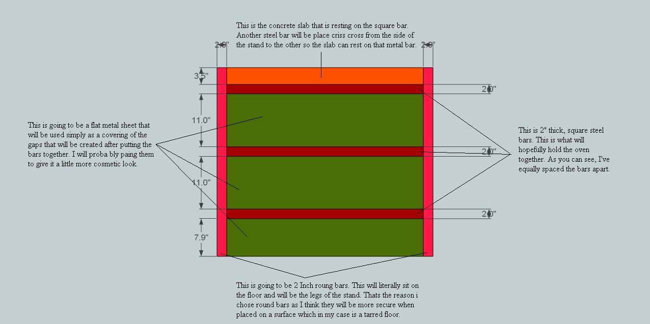
Glad to see the interest everyone has in this tutorial. I guess it can't be helped with the great lessons Gai is providing.I've drawn all that I can think of for now. I colored them in as well and I even got them at the exact dimensions I wish to use.
Can't wait to see how we going to get this in a 3D form.
ThanksRegards
D0me
-
Okay, these are pieces that will have several instances in the model so we are going to make components of them again. Note that though with our "Hide rest of model" strategy, we could work in our original dome model, too, we are now practising a new strategy - when you work with external files and will reload them into the original model later just like another member in this topic.
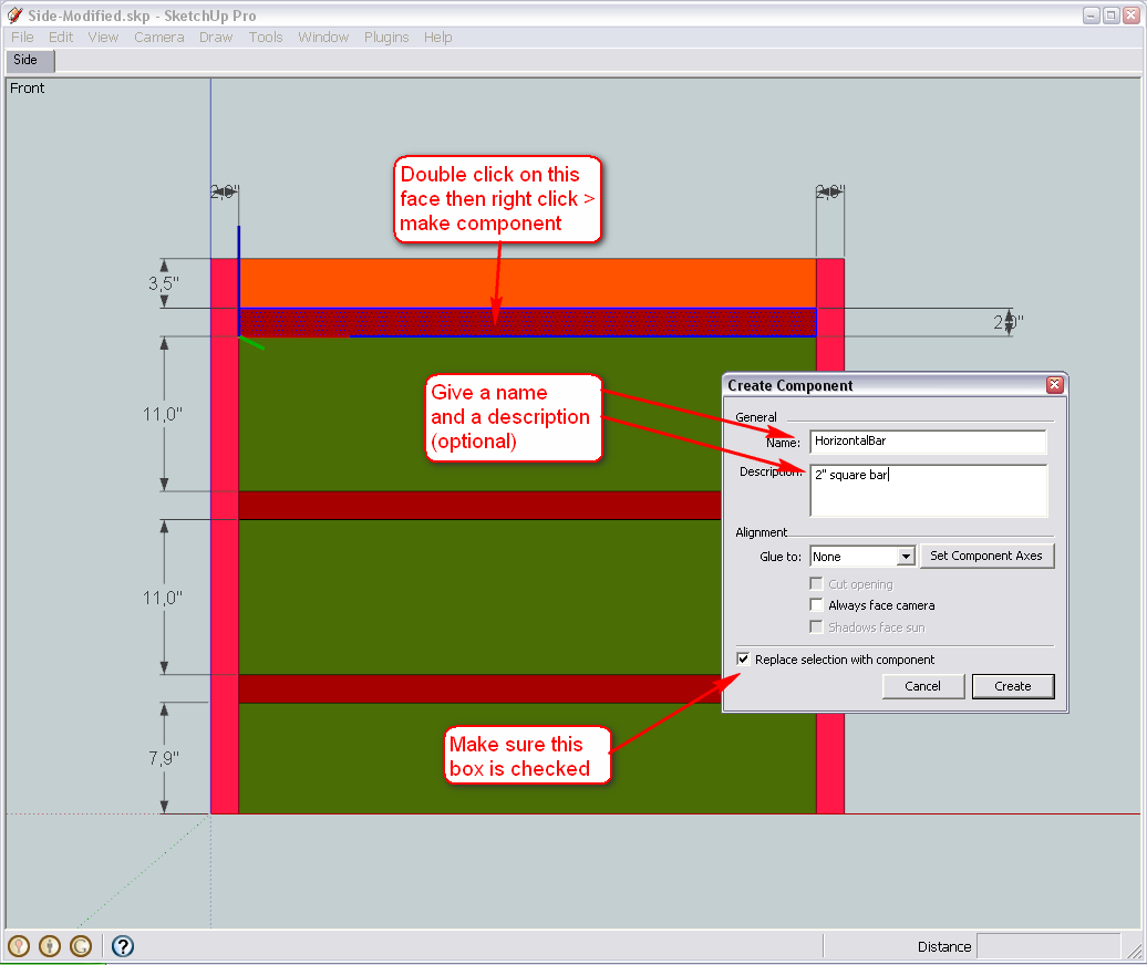
First, let's see those horizontal bars. Select one (practically either the top or the bottom) and make it a component (right click menu). Make sure that the "Replace selection with component" box is checked (this is generally not checked by default when your selection touches other, connected geometry). Give a meaningful name and a description if you wish (these will also appear in the component browser)
Now delete the faces of the two, similar horizontal bars (we are going to replace them with our new component). Select the component then the Move tool and press the Ctrl key. This will make the Move tool not only move but make copies (just like we have already practised with the Rotate tool ).
Move it from one endpoint to the other - then type x2 and hit Enter(this is called "Linear array" - with the Rotate tool, it was "Radial array").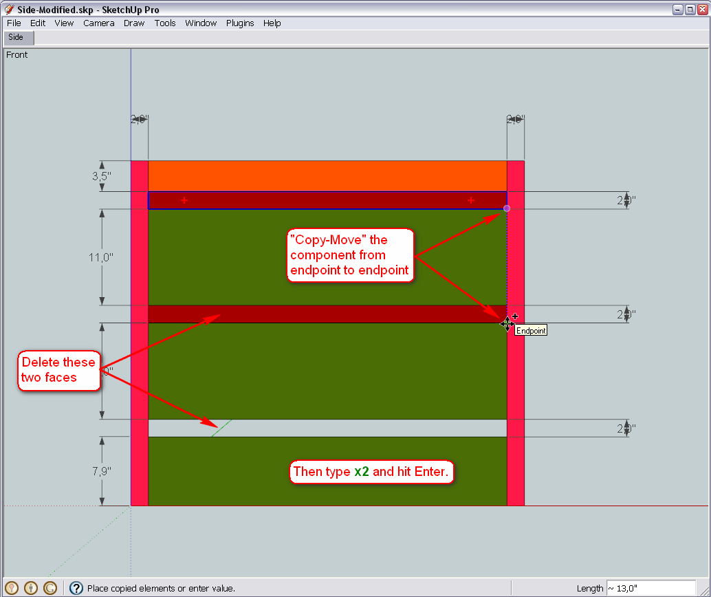
Now do the same with the vertical bars (of course, we are not going to copy more than one instance now) but at the end, also flip the copy around its red axis (as it is oriented in our drawing now - in other cases, other direction would be correct). This is only needed if our component will not be perfectly symmetrical at the end but for now, let's be accurate whatever will happen later.
(BTW what the hack is "roung"? Should it be "round"?)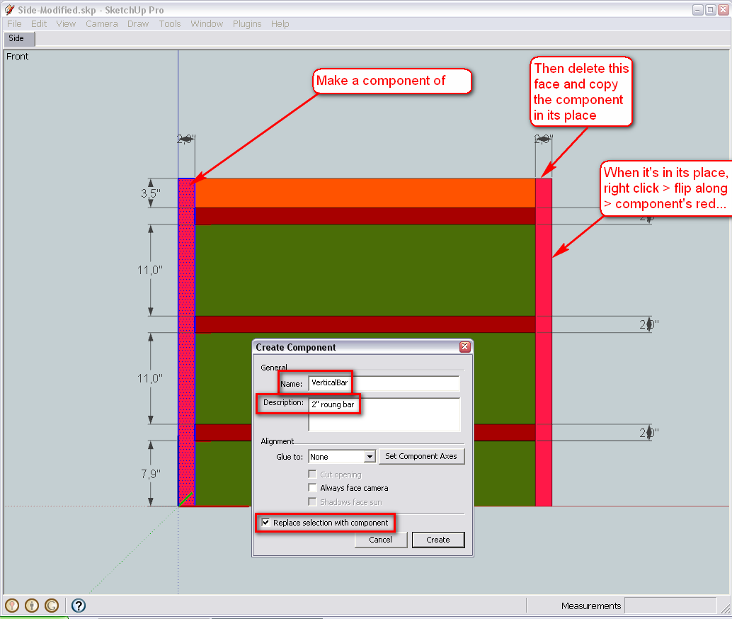
Now comes the two, similar pieces of the siding... Do what we've done above - make a component and replace the other piece with this component.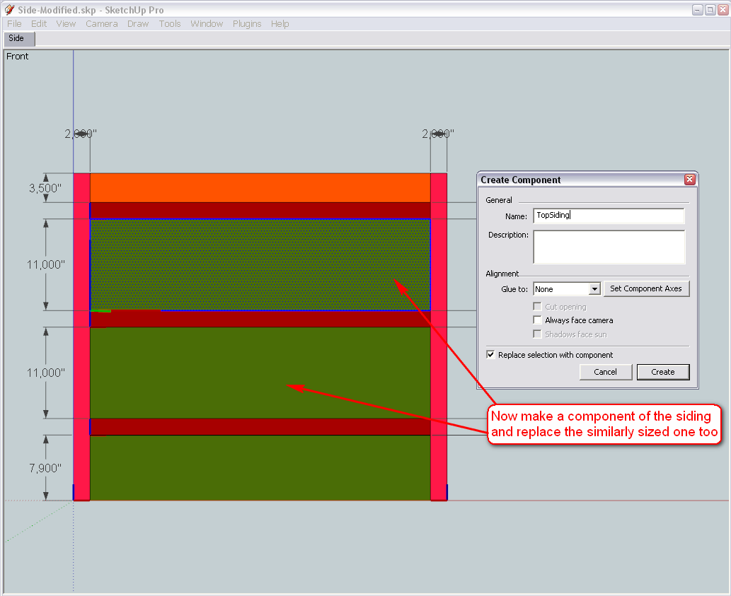
Finally the rest - here we do not Move-Copy anything as these two pieces are individual ones so there is only one instance of either going to be in the model...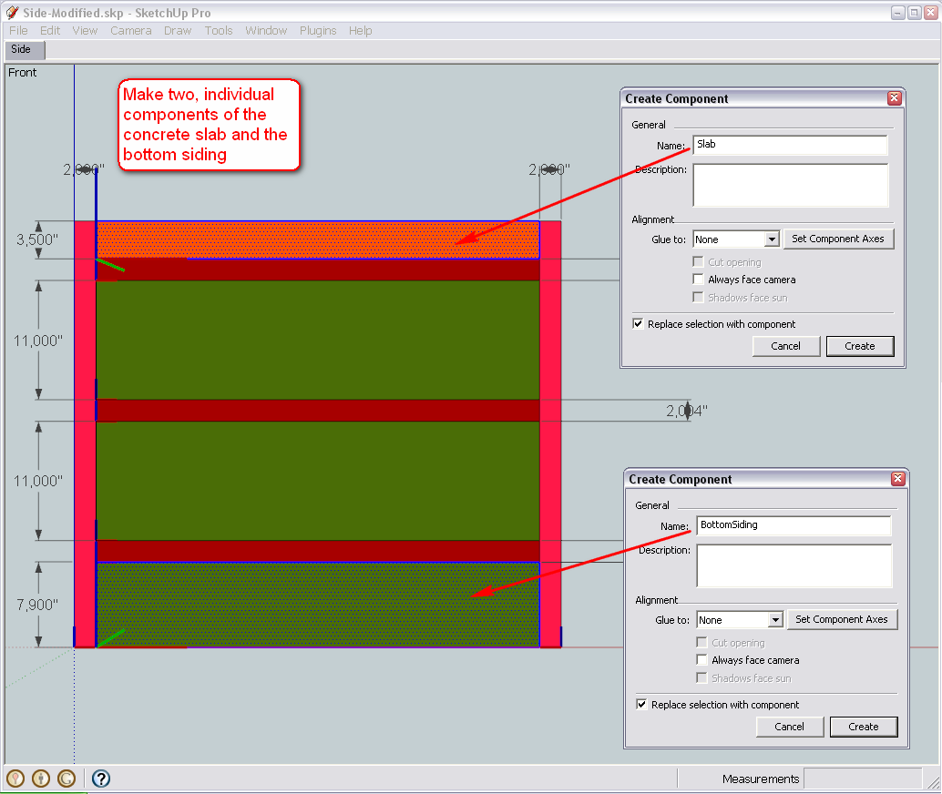
-
Hi Gai
I'm on track now.
After working with the dome, what you made me do makes so much of sense now. Each piece is now components and will much be easier to work with
Thanks
D0me
-
Okay, next, easy step is to open the dome model again (the version where we last made this side rectangle a component and exported it) > right click on that component > Reload... navigate to this one above (wherever you saved it) and open...
What you will see is that inside that side compoent (that we are going to explode soon), all that you modelled in this one, will appear.
One little correction first however - there are 4 instances of the horizontal bar component in your model (instead of just 3). The top one is a duplicate. Select it (clikc on it) - it will obviously just select one of the two - and delete. You will see that there is still one "below" and save your model before reloading like above.
-
Hi Gai
@unknownuser said:
(the version where we last made this side rectangle a component and exported it) > right click on that component > Reload... navigate to this one above (wherever you saved it) and open...
Im a little lost here. Is the version you're talking about found in this post http://forums.sketchucation.com/posting.php?mode=reply&f=79&t=24930&sid=8b51657489c975201327d144508f981e#pr217001 .
If it is, when I right click the Right Side component, I don't get a Reload option in the popup menu. Where could I be going wrong?Thanks
-
Sorry, in this post (originally I may have not uploaded the correct version - just did it myself).
BTW when you post a link, you always post it to a reply window (where you are supposed to write the answer) not to the post itself.
-
Hi Gai
OK, I've managed to reload the picture.
Ready to continue@unknownuser said:
BTW when you post a link, you always post it to a reply window (where you are supposed to write the answer) not to the post itself.
How do I go about doing so? I assume you would like me to post links whereby I can put a description of the link rather than the url address of the link?
-
Hm... Sorry again - I do not know what I screwed up above (more exactly I do - see below - I just cannot imagine how). Your component should've come in vertically. The glitch is in the original model I uploaded and pointed you to - please, use this new one I attach here to redo the whole thing.
I will have to go now and when I come back, we will have a little meandering and side notes about components, skp files and the importance of their axis location (which was wrong in my model).
Otherwise the stand - from here - is really a piece of cake only.

-
@unknownuser said:
Hm... Sorry again - I do not know what I screwed up above (more exactly I do - see below - I just cannot imagine how).
No Problem. I actually saw that the side piece did not fit in vertically but I thought it was normal and we would put it right later. Anyways, all seems fine now. Just one modification I made. The metal sheet covering at the bottom of the stand has been removed. I decided not the cover the piece right at the bottom.
Thanks
-
Okay, now it looks fine. We'll go on from here then.

-
Cool.
Ready to go on.
-
Hi there
Was going through the drawing and remembered you asking me about this@unknownuser said:
(BTW what the hack is "roung"? Should it be "round"?)
It is Round. Is it possible to show this as a round bar to give the drawing a bit more reality?
Thanks
-
Sure - I will go back a bit and modify our "side" component with the appropriate steps. So is the diameter going to be 2" then?
-
Hi Gai
Yes, 2" is fine.
Regards
D0me -
Okay, let's see then.
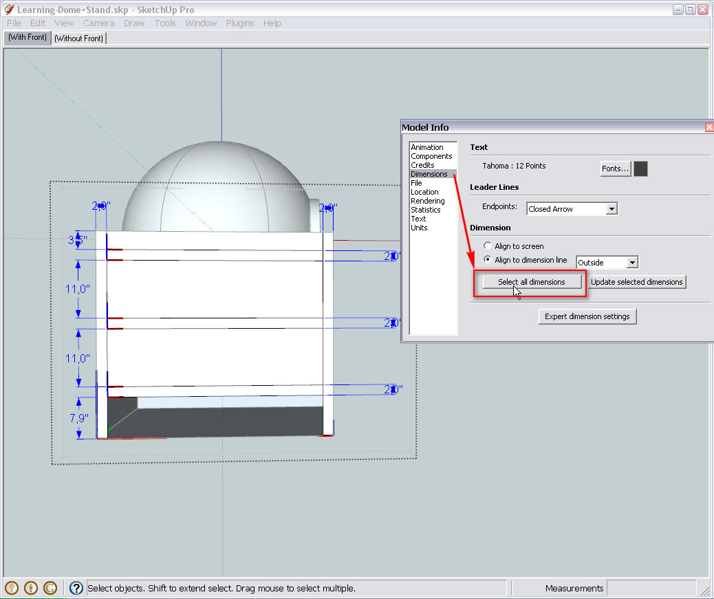
First we get rid of the dimension lines (if we do not need them any more - otherwise just turn their visibility off under the View menu). So enter the "Side" component (double click), go to Window > Model info > Dimensions, select all dimensions and delete them.
Now outside of everything, draw a circle with a radius of 1" (this will give a diameter of 2"). Make sure to pull its radius out along either the green or red (like in the picture) axis. Also, remember that until now, we have always set some bigger segment count to circles and arcs but we do not need to do this in this case as these legs will not be so prominent in our model so the default 24 segments will just do fine.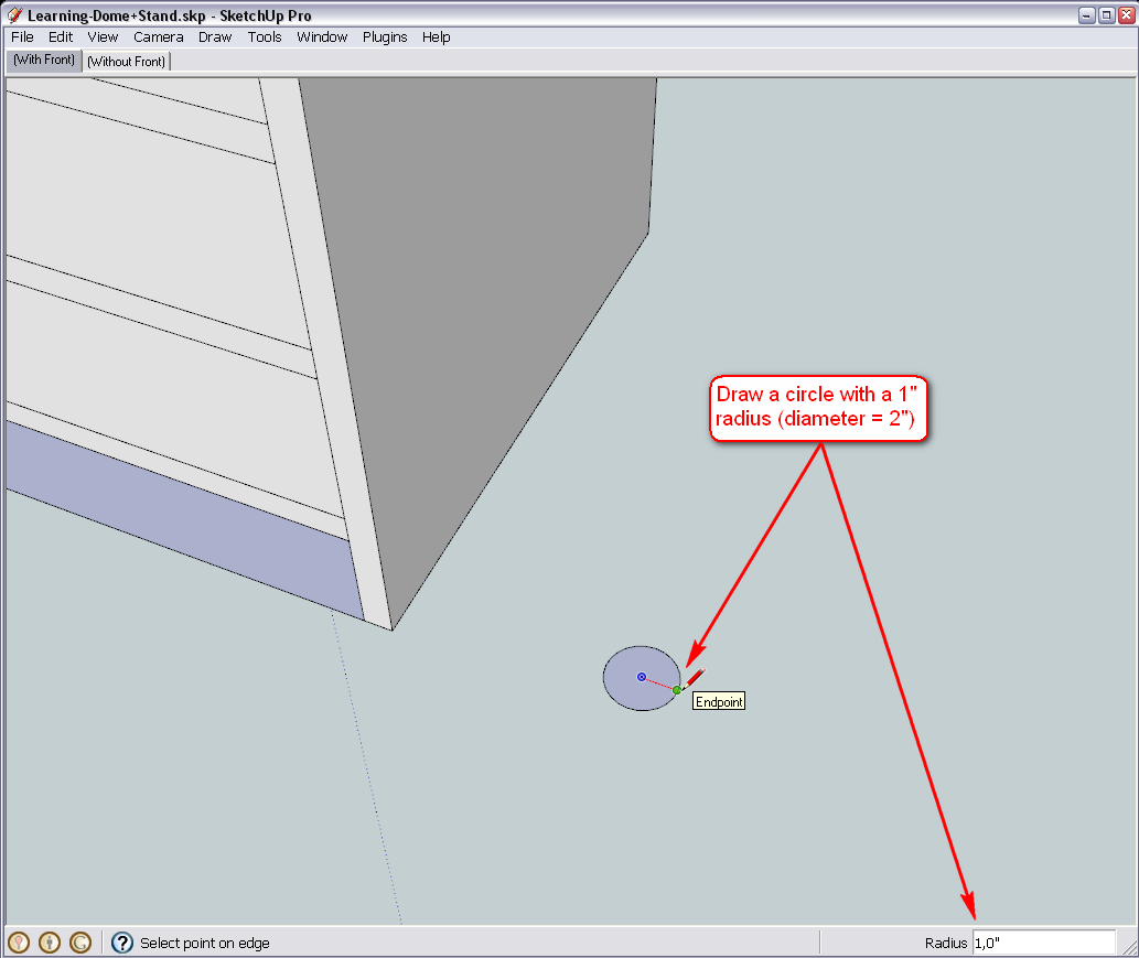
When we are drawing looking down (to get a blue circle), it is drawn on the ground plane (defined by the red/green axes) by default. In our model, it is at the top of the base structure so we will need to PushPull the circle downwards.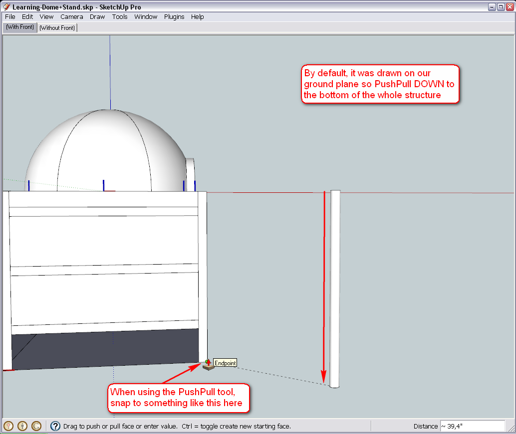
To make sure it won't get "sticky" to other geometry while we are positioning it, select all of our cylinder (triple click), right click and make it a group.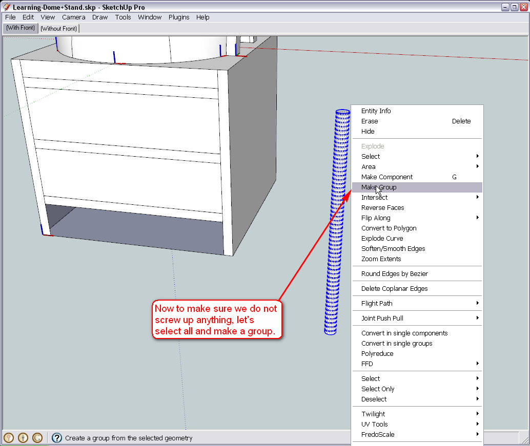
Now simply copy it with the default, Windows copy shortcut key (Ctrl+C), enter entirely into the component of the leg and paste in place for the time being (this is in the Edit menu but as far as I remember, you already have this as a custom shortcut: Shift+Ctrl+V)
Note that we do no really need it here, so a simple paste would do (Ctrl+V) but then we immediately need to position it)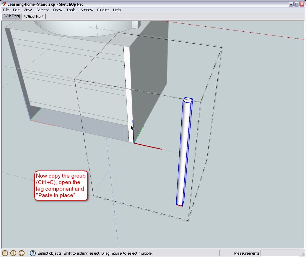
Now select the Move tool find the endpoint that is pointing the farthest to "south" (along the green axis) in the group, grab the group at this endpoint and move it to the midpoint of the face in our component.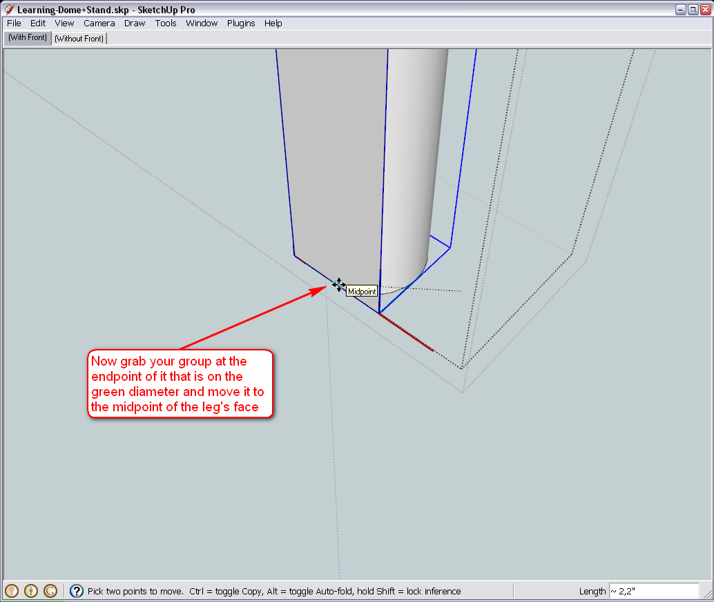
Now double )or even triple) click on our "old face" and delete it as we do not need it any more.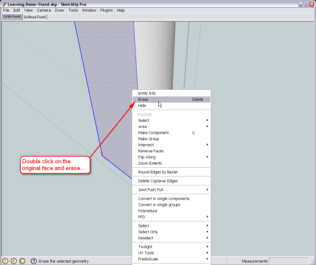
You can also explode the group - its geometry will now replace that of our old leg component (in both instances in the model)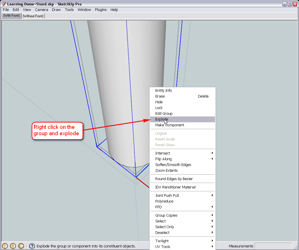
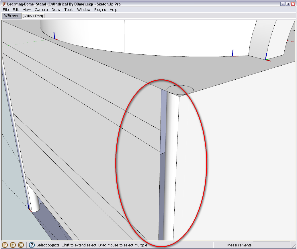
After exiting the component, this is what you are supposed to see. Not perfect yet (the round leg affected how the other components look in relation to it) but we will handle that later.
Delete our temporary cylinder group.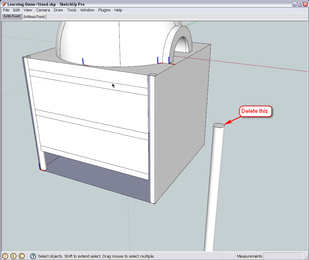
Here is the model how I have finished it - for a reference (I think the biggest issues with mistakes and such come from all these different versions and when we incidentally mess up whcich one to go on working wioth )
)
-
Hi Gaieus
I've done the following but was unable to proceed further after my point number 5.
- I drew the circle along the red axis.
- I pulled the circle downwards and snapped it to my right square bar that is currently there and the tool tip "Endpoint" appeared
- I made the newly created cylinder a group by triple clicking.
- I then clicked the cylinder once and pressed ctrl+c
- I then double clicked the side group to get inside of it and then I double clicked the square bar (leg). I then went to Edit > Paste In Place. I now notice a bar on my left side that's also created.
I've cant seem to proceed any further.
Every time I try to move the cylinder to the midpoint of the leg, it somehow dosent snap to it or offsets the side piece completely. I've been at this since last night but just cant seem to get any further . Please tell if so far I'm on the right track as knowing me, I probably did something wrong when creating the cylinders and that's the reason i cant get any further.
Thanks
-
@d0me said:
- I then double clicked the side group to get inside of it and then I double clicked the square bar (leg). I then went to Edit > Paste In Place. I now notice a bar on my left side that's also created.
That is good - it means that you succeeded to paste the group into the component itself - and since we have two instances of the same component, and editing one will change the other one, too (that's actually the point here).
Okay, now we will make our jobs a bit easier. Let's start using guide lines (that's what they are for - when you have complex geometry around, you pre-define paths, distances etc with the ape measure tool : - just click on one then the other point with it...)
Here (beside moving the group a bit closer for better screenshots), I established a guide line between the endpoint we need in the group and the midpoint of the face we want to move the group to:
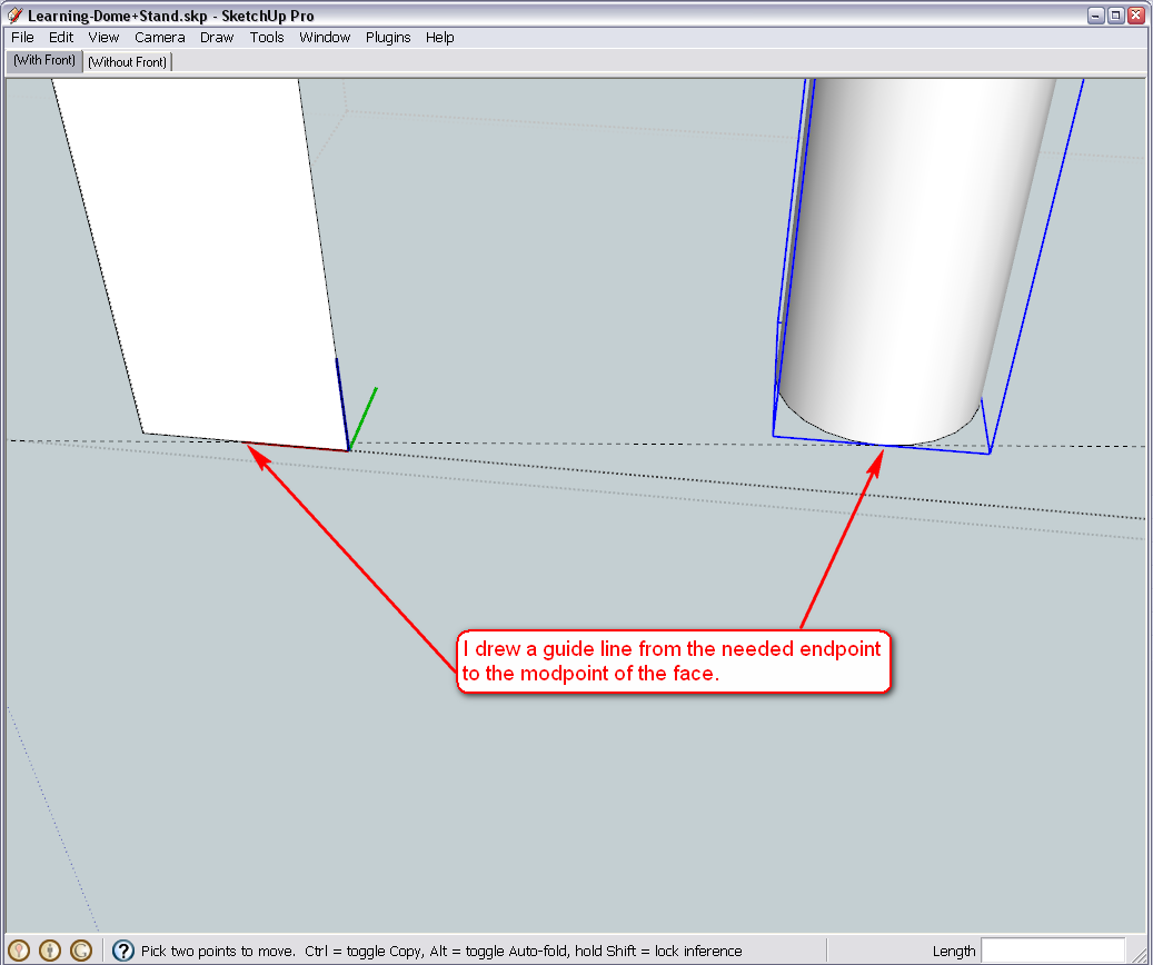
Now if we start moving the group, we can easily get an "On line" inference - and that is exactly the direction we want to do it: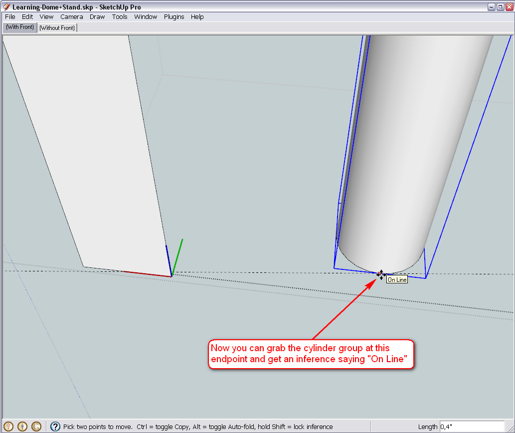
If you now press the Shift key (and until you keep it pressed), the operation will be locked on this direction - you can even move the cursor away - the thick dotted line indicates the direction of move: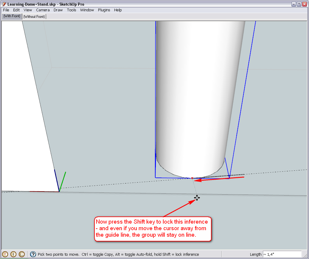
Now either without the Shift key, snap the move to the "Intersection" (of the Midpoint and the Guide line):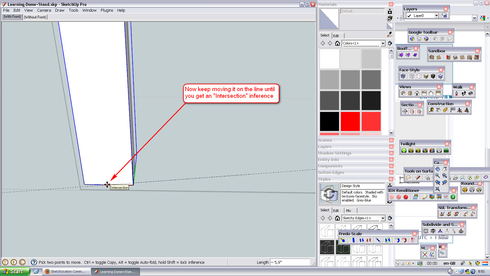
Or while the Shift key is still pressed, get a "Constrained on line" intersection at the Midpoint (notice that in this case, as far as the "sensitivity" of the inference engine allows, you can even move the cursor away a bit from this midpoint):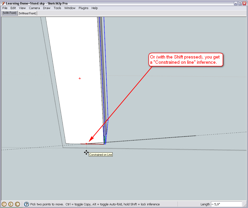
Here is the file at its state of the first image - so try to practise all the steps above from that point.
-
Hi Gaieus
I have to be honest and say this was the first time during this entire tutorial that I became frustrated to the point of quitting but you have really been patient enough to provide alternate solutions to every problem I've encountered. A true teacher indeed.So far this is what I've done.
- I double clicked the side group to get inside of it.
- I then double clicked again to get inside of the cylinder and leg group
- Using the tape measure tool, I managed to find the endpoint on the cylinder and drew a guideline to the midpoint of the leg. A note at this point: It didn't say midpoint but a measurement appeared with a blue dot that normally appears when its at the midpoint. I assume that this is correct and the reason it didn't show "Midpoint" is because of using the tape measure tool.
- I then used the move tool and hovered over the cylinder until i got a inference saying "Online Outside Active"
- I then moved the cylinder to the leg until i got a inference saying "Intersection".
- I then clicked on the face of the leg that was there and deleted it.
- Lastly I double clicked the side to get back into the group and then double clicked the cylindrical face, right clicked and selected explode
So far everything looks right but you'll be able to tell me whether its right in terms of geometry.
-
Okay, glad you finally got it.
To tell the truth, first I planned to do it differently but ran into something that (I believe) is a bug. I don't want to go into the details now (maybe we'll discuss it in the Bug Reports subforum once I'll have fully gone around to explore) but definitely did not want to drive you into this bug at this stage.
Also, we could have exported the whole side component ("Save as..." method) and then reload later - but we have done it already so I wanted to do it differently.
Anyway, you seem to have done it perfectly so far.
Now we are at a point however where this last modification brings up some questions. What to do with those gaps, how thick those horizontal, rectangular bars should be, where exactly the round legs should be in relation to them and also the siding panels...
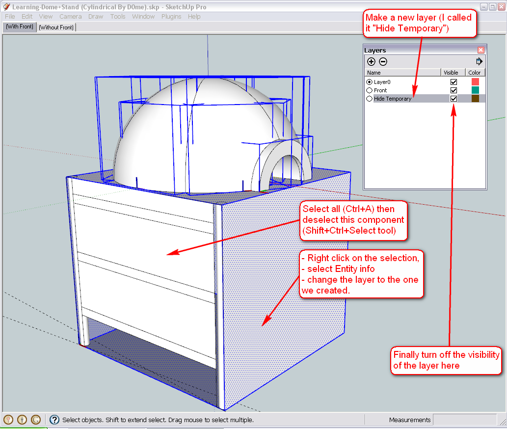
So now we make some preparations in order to be able to work easier in the model (without the export/reload function). Let's make a temporary layer where we simply hide everything that is not needed now. Open the Layers dialog from the Window menu and add a new layer with the + sign.
Then select all in the model (not only SU shortcut but Windows in general: Ctrl+A).
Now "deselect" the component we want to work with. Use the select tool (by default, the shortcut is the Space bar). Test the different modification keys:- Shift + = add/remove; indicated by a +/- sign
When using this, clicking on something will toggle its selected/deselected state. - Ctril + = Add to selection; indicated by a + sign only.
Use this when you are sure you only want to add anything you click on (and not deselect something incidentally) - Shift+Ctrl + = deselect (remove from selection); marked by a - sign.
So after making sure that everything BUT the side component is selected, right click the selection, go to Entity info from the context menu and assign this layer to the selection. Then turn off the visibility of the layer so that we can work easier.
%(#BF0000)[Note however that we have done something you should never do - put "raw" (i.e. not grouped or "componented" geometry other than Layer0) and this is a very bad practice - never do that. Always group everything you want to put on a different layer and only "move" the geometry there.
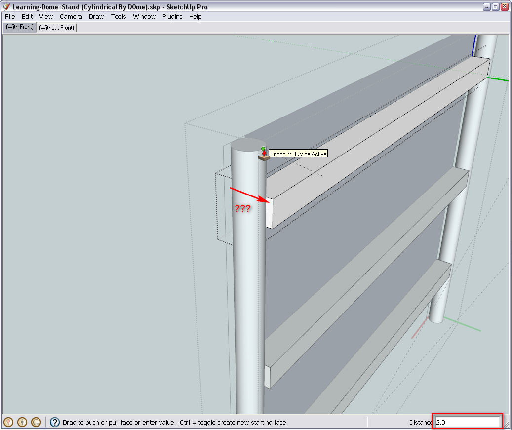
Now we could only do it because we are going to delete this layer later and on that occasion, will move everything back to the default layer..]Well, and now the question you have to think about - how thick should those side bars be? Here I edited one and PushPulled it to the exact thickness of the round leg - i.e. 2" - but this is just for the demonstration (also notice that the other three became modified as well).
- Shift + = add/remove; indicated by a +/- sign
-
Hi Gai
I have added the rest of the model to the new layer and hid everything except the side.
I have also pulled out the square bar by 2" and 2" is fine.
The round legs should touch the square bar as in reality it will be welded to each other. The side covering can be pushed back slightly so it sits flush against the inside of the round legs which is the same spot where the ends of the square bars touch onto the round legs and this should indirectly take care of the gaps.
Can we create scenes for the side coverings so I can choose to display or not display it?
Lastly I notice that underneath the stand, there is a covering. Can this covering be moved up to touch the last horizontal bar?Thanks
Hello! It looks like you're interested in this conversation, but you don't have an account yet.
Getting fed up of having to scroll through the same posts each visit? When you register for an account, you'll always come back to exactly where you were before, and choose to be notified of new replies (either via email, or push notification). You'll also be able to save bookmarks and upvote posts to show your appreciation to other community members.
With your input, this post could be even better 💗
Register Login


Advertisement