Factory Layouts
-
I do a lot of pre-sales vizualizations, and sketchups:
Earliest concept: 12 SCARA robots!
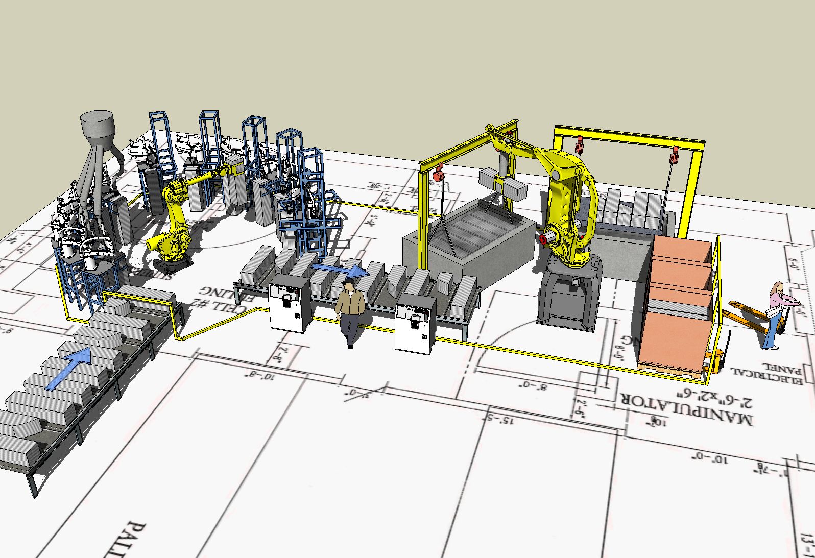
Custom robots replace SCARA robots:
Near-final:
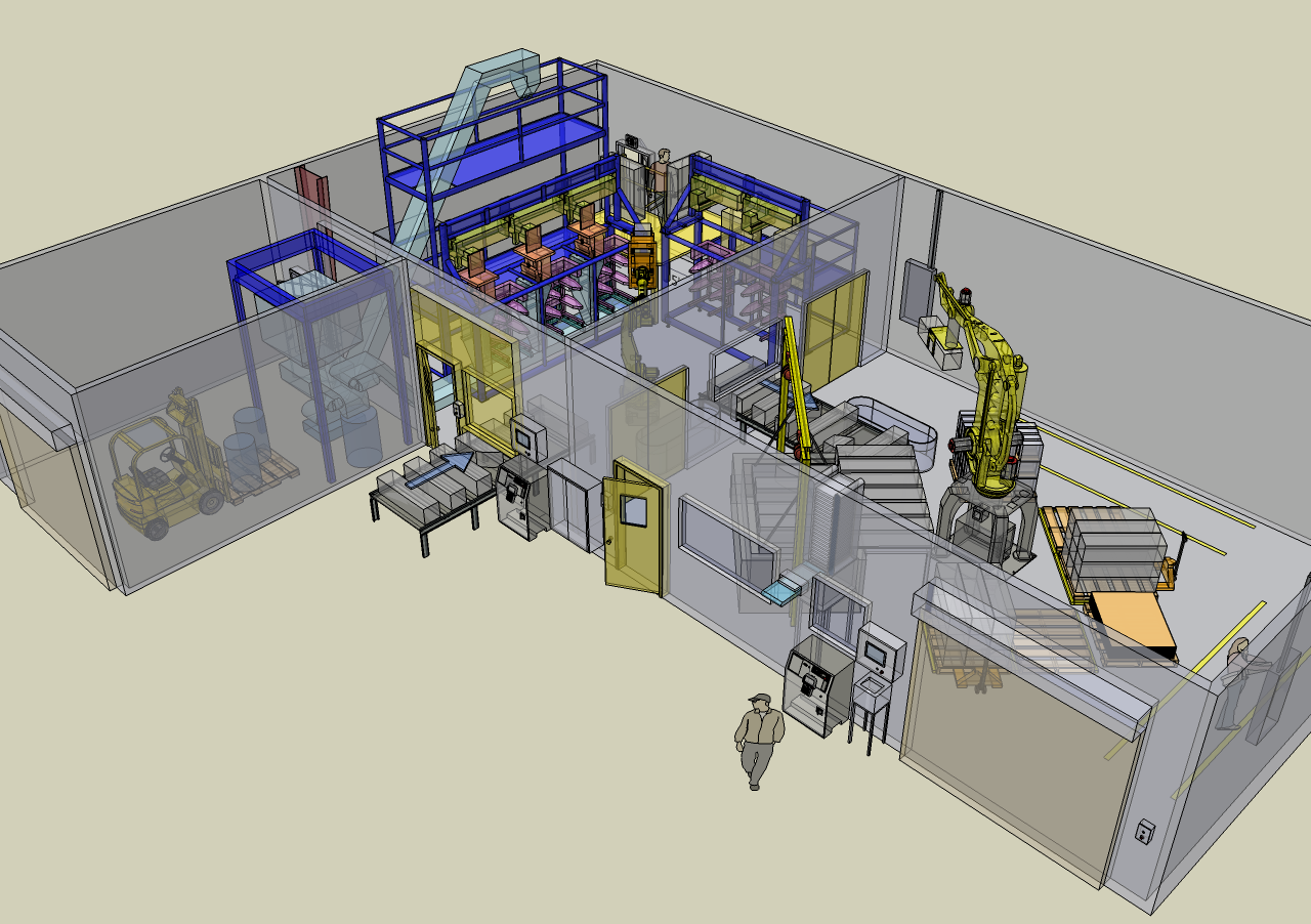
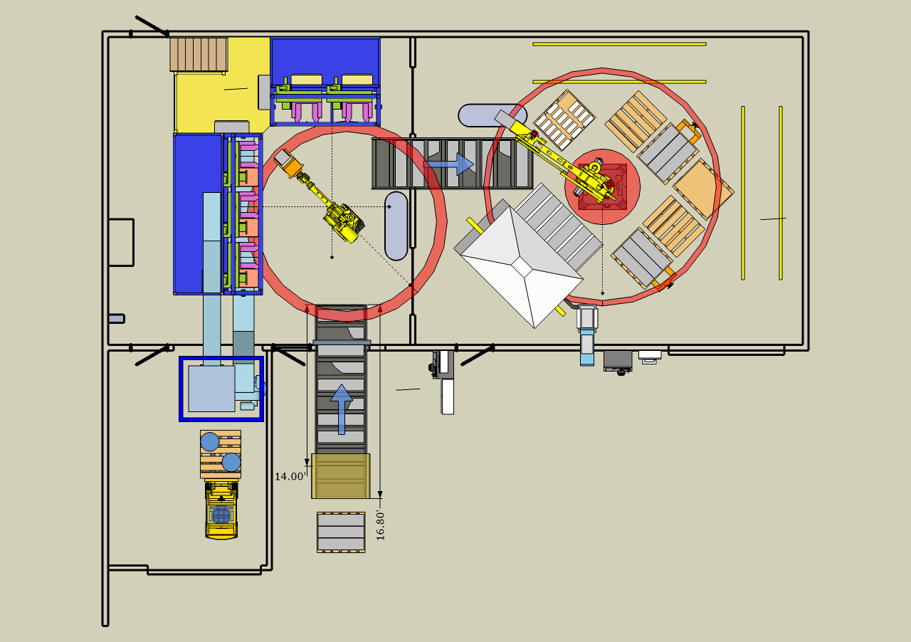
Hypershot 1.8 Demo screenshot-render, not so impressed with the experience:
Almost every system inside the two rooms, and the stuff outside of the rooms was designed or integrated by my company to replace a purely manual process. The actual machinery is of course a good deal more complex than is shown. The geometry used is mostly simplified representatives of our equipment, with the exception of the yellow industrial robots, which are Solidworks imports of the manufacturer's CAD, though I'm sure the CAD they provide is just complex enough for their sim software, user's integration design work, and their user-manual illustrations, and NOT their actual manufacturing CAD data, or SU would explode. As it is, I wish their CAD models were much, much simpler.
I'll post different factory layouts later,
-
Dear Jay,
A very nice presentation. What exactly does your company supply?
Regards,
Bob -
Hi Jay,
Do you upload your models on 3d Warehouse? Or are the components already designed on the 3d Warehouse by other users?
The reason i ask is because i'd like to see the robot models more closely. I didn't see any links on your site to view the models?
Other than that it's very impressive
rgds,
Rich -
@jaycephus said:
And we're also producing some custom multi-axis underwater positioning systems for use by an international entertainment company.
That sounds like Cirque du soleil to me!
-
I'm glad you asked.

The company I work for is called ARM Automation, located in Austin, Texas.
We do the design, integration, build, and programming of factory automation, such as the robotic manufacturing equipment shown above. (I personally also do controls design, and programming.) We use industrial robots, custom-designed robotic systems, machine vision, servo-motors, motion controllers, etc. with our own custom-designed equipment to provide automation solutions to various kinds of manufacturers (or other kinds of companies). We're currently finishing the system shown above, and we're also producing some custom multi-axis underwater positioning systems for use by an international entertainment company.
We've done a lot of work for a certain local major computer manufacturer, a major chip manufacturer (the edible kind), and various sorts of food, petroleum, medical, and goods manufacturers.
-
@chris fullmer said:
That sounds like Cirque du soleil to me!
Not quite...

This page has some good info on it... scroll down to the second stop sign and look for descriptions of the tech used in the 'attraction'.
-
To Rich above:
The models in the layout above come from multiple sources. Some were made in Sketchup by me. The forklift and pallet-jack came from the Warehouse. At the point in time that the above layout revision was produced, some work had already been done in Solidworks, so some of the custom machinery in the room to the left is a simplified model of the equipment assembly in Solidworks, exported and converted to something that imported into SketchUp. At that time I think I was going from SW to 3DS to SU, but now there is a more direct solution. The earliest revisions of this layout used my own SketchUp models for our custom machinery. Some of those revisions used a SCARA robot at multiple positions. It might be interesting to post the earlier revisions to see the progression from first concepts to the above near-final layout.
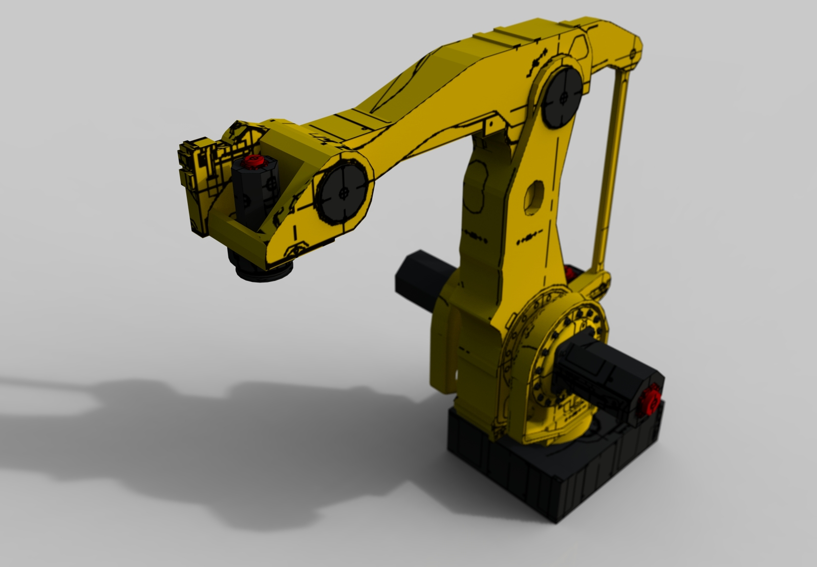
The robot models are also from Solidworks, originally created by and downloaded from the robot manufacturer as Solidworks files. I never put the robots in the 3D Warehouse because I wasn't the creator, and I wasn't sure that the manufacturer would allow it. They are pretty touchy about their information and I might have had to agree to some legalese BS to originally download them. If I'd created them from scratch it would be a different story.
If I can find them already in the public domain or verify that they are not 'controlled', then I'm thinking I will joint them up in SketchyPhysics and upload them. Currently, they are merely grouped with some extra axes thrown in to make them a little easier to pose.
Here is the very first fast and dirty robot SU model I made for the very first SketchUp layout I did for a client called the United States Bureau of Printing and Engraving, otherwise known as the Greenback Factory.

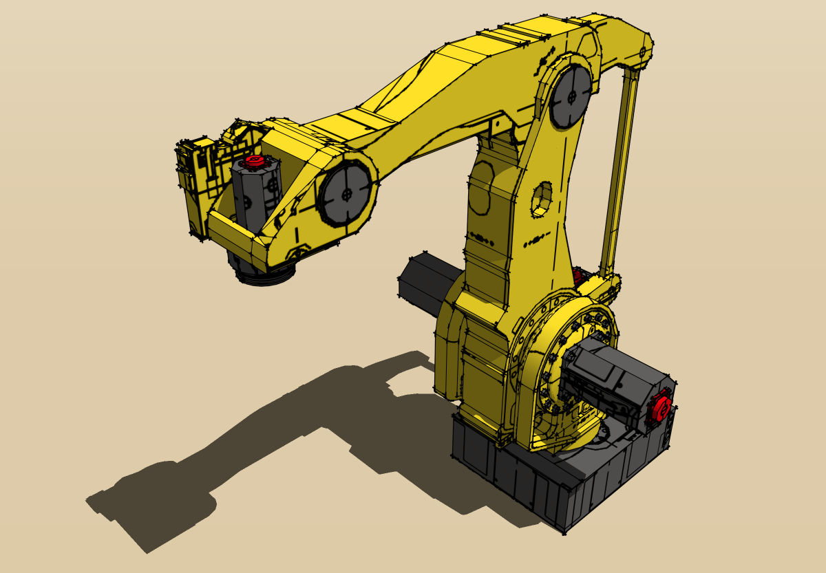
And with the Hypershot demo, LOL:
-
Dear Jay,
You mentioned exporting from SW and importing into SU. What is your preferred method?
I use AutoDesk's Inventor, and my preferred method is to export from Inventor as a .sat file, import into AutoCAD, scale by x 100 to take care of the small features, export as a .dwg file, import into SU, then scale back by .01. It doesn't always work, but I do not know of a better way. Any suggestions.
Kind regards,
Bob -
Hi Bob,
I've used the demo of RightHemisphere DeepExploration CAD Edition originally, but never bought it (who comes up with their names? Worst marketing decisions ever.)
It could open SW I think (or maybe just IGES, can't remember), and export 3DS originally, which imported into SU pretty well, with maybe just a bit of tweaking required every now and then. Now DE actually exports in the SU .skp format.
Now, I have a license of IronCAD which I use purely for its translation abilities from Nurbish formats to polygonal formats. I also have to take SW and SU models into other software such as various proprietary robot simulation programs.
I've never tried .sat from SW through AutoCAD into SU.
-
Dear Jay,
Thank you for your detailed reply. That is very helpful. I get a lot of stick at work for using SU for concept and preliminary designs instead of going immediately to Inventor. They do not like the fact that one cannot export from SU into Inventor.
Keep the images coming.
Regards,
Bob -
Bob,
For us, I would say it is speed, speed, speed. Solidworks 9 is a massive improvement, no doubt, on speed over older versions (including UI interaction speeed), but it is still cumbersome to make individual parts and assemble them up compared to working in SU. If you do it the fastest way possible, you end up with something that subsequent engineers will just throw away anyway because it isn't mated up properly, built with future modification in mind, or made with the particular manufacturers' models that they will end up using, and so on. Why waste time designing a robot end-effector in SW for a proposal when the final end-effector NEVER looks like the one in the original proposal. It's best to go for speed and appearance, and let the subsequent engineers worry about precise function. One exception would be if we are cutting payload ratings close, and need to know precisely what a realistic end-effector masses during the proposal stage. Then we would need to put in more design work, build it in SW, engineer in all the pneumatic cylinders, etc., so we can get a pretty accurate idea of the mass in order to select the cheapest/smallest robot that will do the job. (And then the client forgets to tell us that their whole product is made of stainless steel and weighs twice as much as they originally told us!
 )
)And of course the pre-sales design is a moving target, as shown in the progression in my first post, so being able to blow away half the layout and quickly redo it, tweak positions on the fly in meetings, and so on, are all important.
I've done pure SolidWorks projects too, but this has been only because I needed inverse kinematics solving on a 6- and 7-axis industrial robot arms to verify reach and check interferences. I'm just getting into SketchyPhysics, so I may end up back in SU for that kind of thing as well. It may be that SU + SP >= SW, at least for quick studies, and then for the more precise cycle-time analysis robot studies, I would need to use the robot manufacturers' simulation software anyway (another layout that doesn't convert back into SW even if it started in SW).
And over the past couple of years, we've been continually pushing against the number of SW licenses we have, so getting a seat of SU at a tenth of the price of a seat of SW is a factor.
-
Dear Jay,
Perhaps you could make a list of all the new features you would like to see for Sketchup, ones that would help you with quick mechanical design. There is a volume calculator ruby which I have found useful for calculating masses (look in the Ruby section).
Here is something I used Sketchup to design:
http://forums.sketchucation.com/viewtopic.php?f=81&t=15910
The machined base is made from polymer concrete, which is all rather excited as I have never designed with this material before.
Kind regards,
Bob -
Bob, that is an extremely good SketchUp assembly, and a very nice job. Personally, If I have access to SolidWorks, there is no way I would do that particular job in SketchUp. There is enough mechanical detail and repetition that the advantages of SW trump any advantages that SU has, and I believe you would be faster, with much better drawing output, in SW. Just having to keep in mind how many edges I need to use for a given cylinder or hole would be bad enough. But the three lobes could be treated as a pattern, and you would only have to work on one of them. The other two would update automatically. The history-based feature concept really takes the win here. As you build up the assembly in SW, you can have one piece rely on the shape/dimensions of another piece to drive it's own shape/dimensions. This makes the assembly 'smart' (well, as smart as the designer who has to build the 'intelligence' into the design, of course), meaning that making a change to a critical part would ripple changes through the design automatically (and any drawings already created would also automatically update, though they would still require tweaking at minimum). And you needed to make a mold as well! SW has built-in tools for that, though I've never used them. Given that the mold was built instead of machined, you probably would just use the standard tools in SW, not their mold tools.
Of course, SU PRO is almost as little as a tenth of the price of SW, so that can be a factor, but when you use multiple seats of SW year-round, and try to do your projects with as few engineers as possible, then doubling employee productivity is far more important than saving a few thousand up front. Of course, it all depends on what you're doing. As I stated previously in this thread, I believe SketchUp is a better tool than SolidWorks to do initial layouts and proposals (just like them fancy-schmancy architects
 ).
).At least with the new Component features in SU 7, there are probably more cases where mechanical design can be done in SU as quickly as SW, at least until the drawing stage. But performance in SU 7 has really degraded on my systems.
The biggest request I have would be SPEED. SU has concentrated from the beginning on UI speed, which is an area where SW and PRO/E and most others have really suffered. Now SU needs to bring their polygon-handling speed and capacity up to the level of other polygonal modelers, which is an area where SU seems to have gone backwards. A 400K-entity model should not bring a 64-bit hyperthreaded, 4-core i7 CPU, dual-GPU, 6GB RAM system to it's knees. And that's with just basic hidden-line rendering. SU needs to step up with speedier real-time rendering of their current NPR features. It's gotten to the point where their real-time NPR needs to be treated as non-realtime, only turning it on at the end of the project. Third-parties have provided some pretty good stuff along the lines of quick photo-realism and realtime rendering, but it would be nice if SU had it's own native ambient occlusion real-time renderer.
And yes, I learned long ago about every possible trick (components, layer-switching, etc.) to allow me to pack more entities into a project. But I've opened old projects in SU7 that I created originally in SU 5 and 6, and they seem to be far more sluggish now. Could be faulty perception. I would need to install SU 6 and 7 on the same system and try them one after another to verify it. But I AM certain that SU 7 has not gotten faster.
BTW, have you ever made a pure hole component? I'm not sure that such a component would give you the geometry-overhead savings of a normal component, but I have made a counter-bore hole/hex-head cap-screw component that 'cuts' into the surface (like a door or window, of course). I assume you could make a blind or through counter-sink or -bore hole as a component as well. Have you made one that is configurable using the features in SU 7?
It's nice to talk about SU from a mech designer perspective, so feel free to bring up any tips or issues here.
-
Dear Jay,
Yes I know, but I got carried away. I have been using SU for the design concepts (because I find it quicker), and I'm almost ready to switch to Inventor for the rotor's component parts. After designing the machine base and load spreader using SU, I quickly redrew the component parts in Inventor, which then lead to the 2D drawings for manufacture. I must say that my Inventor models, being feature based, are much cleaner using this approach, and I get fewer conflicts when making changes as I know what I want to draw and how to draw it.
Why do I like modelling in SU? Because I can chop and change without worrying about the constraints placed on the features making up the model. Making the lobe/outrigger a component ensures that changing one changes all three, and so not a lot different to SolidWorks or Inventor.
I think it all stems from my background as I learned to draw on a drawing board (pencil and drawing film), and then migrated to AutoCAD 2D. When the department switched to AutoDesk's Inventor (which comes bundled with AutoCAD) I found the transition from 2D to 3D very difficult and so tended to rough out my ideas in AutoCAD before switching to Inventor. Discovering Sketchup and it's very user friendly interface I quickly became hooked on 3D modelling. I just need to hone my Inventor skills now so that I find modelling in that software as intuitive as modelling in SU.
Using Inventor's parametric modelling attributes is obviously the way to go, but unlike your good self, most of what I do is a one off and so the overhead of not using parametric modelling is very small.
The making of the mould was left to the pattern makers at Granitek (http://www.granitek.co.uk/index.htm) as it is a highly specialised process requiring alchemy as well as engineering.
No, I haven't made a pure hole component, but it is an idea I will try out. I have made some thread textures which I find useful for showing what is a clearance hole and what is a tapped hole. The texture only works if the upper and lower circles defining the hole are true circles. If the circles are exploded into segments then it won't work. You can find the textures here
http://forums.sketchucation.com/viewtopic.php?f=40&t=11378&hilit=+thread
They could be improved, but I hope you find them useful.
Kind regards,
Bob
Advertisement


