Any ideas for a solution?
-
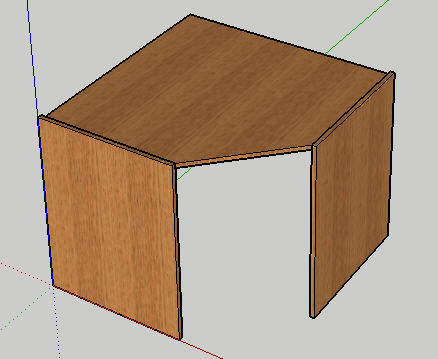
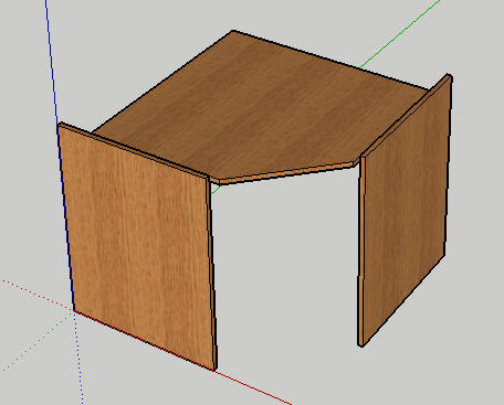
Attached below are two images of a component.
The component is made up of 3 sub-components - a top and 2 sides.One of the attributes options is to change the 'inset' which controls the position and size of the top (the sides remaining static).
Everything in the attached model works except the diagonal cut at the front (see second image) the ends of which need to always be in line with the ends of the sides.Does anyone have any ideas about how this could be done, if indeed it is possible in Sketchup?
-
Its a bit long winded, but you could probably do it by making each individual face of the top a component and adjusting it like that.
-
yeah, changing the shape of geometry is outside the scope of DC's. That is into ruby territory. So you would have to do it by dividing the top board into pieces that can be scaled separately. Think of it like this:
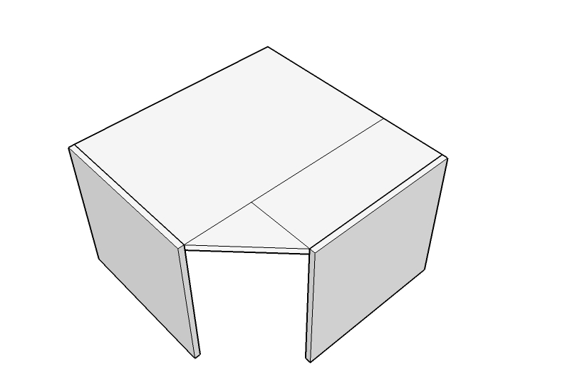
Then the triangle piece always stays the same but you scale the 2 rectangles as needed. You would also hide the lines you dont want showing. Hope that helps,
Chris
-
Look this maybe useful:Nriiul Dia kahe riiuliga.skp
Budla. -
Thanks Guys.
I had another configuration that needed a solution and started to consider breaking that up into sections.
Before I had time to address it your replies came in thick and fast and now I can see a way of doing them both.I just have to figure out the maths to make sure they work parametrically as they should.
Thanks again.
-
OK, all my models have been adapted and work perfectly for sizing etc.
But I now have a question about textures.
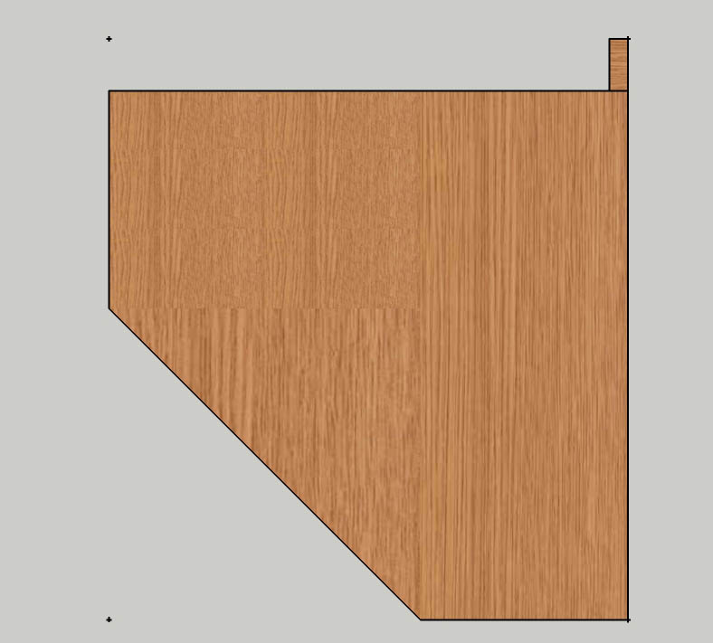
The image below shows a typical configuration of 3 separate components.
All have the same texture applied, but the texture shows differently on the three parts.I realise that the tiling in the grain direction could be an issue as the components have different lengths and the triangular piece is not a multiple of the texture image size, but I don't understand how the grain width is being shown extended differently on all three parts as if the texture image is being stretched instead of tiling.
Any suggestions?
-
@peweuk said:
OK, all my models have been adapted and work perfectly for sizing etc.
But I now have a question about textures.
The image below shows a typical configuration of 3 separate components.
All have the same texture applied, but the texture shows differently on the three parts.I realise that the tiling in the grain direction could be an issue as the components have different lengths and the triangular piece is not a multiple of the texture image size, but I don't understand how the grain width is being shown extended differently on all three parts as if the texture image is being stretched instead of tiling.
Any suggestions?
[attachment=0:df9100ga]<!-- ia0 -->problem texture - tiling.jpg<!-- ia0 -->[/attachment:df9100ga]
Yes it is problem for me too?
Maybe Ruby guys help us? -
Unfortunately, there's not an easy way to do what you're talking about. As you scale things like this your textures will start to line up poorly. One could imagine a ruby script that fixes this, but it wouldn't be particularly easy.
Better texture support is a common feature request for DCs, so it's good to see a concrete example of why it's needed. Wish I had a better answer for you.
Cheers,
Hello! It looks like you're interested in this conversation, but you don't have an account yet.
Getting fed up of having to scroll through the same posts each visit? When you register for an account, you'll always come back to exactly where you were before, and choose to be notified of new replies (either via email, or push notification). You'll also be able to save bookmarks and upvote posts to show your appreciation to other community members.
With your input, this post could be even better 💗
Register Login


Advertisement