Help with DC scaling issue
-
I'm trying to grasp the nuts n'bolts concepts for dynamic component creation, but can't seem to find much documentation on seemingly simple issues. I've printed out the dynamic "fence posts and rail" tutorial, which is a similar concept, but cannot seem to apply that to my goal below.
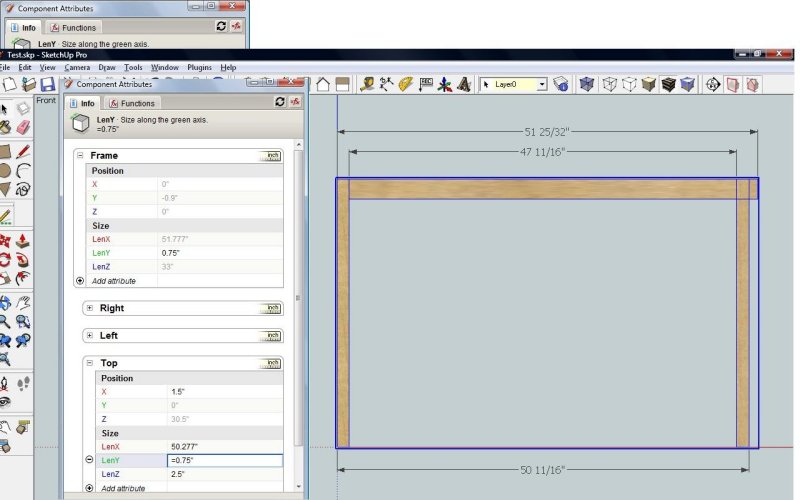
The goal is make the "top" rail sub component in the component "frame" below, fit precisely between the two stiles when the model is scaled to different reference points.
Theoretically, I'd like to be able to scale the frame between two locations/reference points, in both lenX and lenZ. The ultimate objective being to have a dynamic component "face frame" which can be used to design a line of cabinets with regard to size, and which are in other than industry standard 3" widths (I build all my cabinets using the "face frame" as the base/starting point, instead of vice versa).
(Note: I've left out an intended bottom rail for simplicities sake during my early efforts, as one less sub component to deal with).
AFAICT, the proper constraints have been added to each of the three subcomponents, as well as the component Frame itself.
There are three issues I'm struggling with:
Getting the top rail to consistently scale properly between the left and right stiles; none of the dimensions seem to add up to the various formulas after the scale; and, during scaling, it seems that upon release of the mouse to complete the scale at the intended reference point, there always seems to be a slight shift, either away from or toward the intended reference, causing the intended dimension to be off.
If someone could give me a nudge in the right direction, I would appreciate it.
My mind is apparently starting to feel my age, so be easy on me ...

Thanks
-
Never mind ... I figured it out:
THINK: "X" +/- ... sheesh!
Position is everything ...
-
For those who find themselves wrestling with the creation of dynamic components, start here:
Explained in minutes what took hours ... just to find the link.
Hello! It looks like you're interested in this conversation, but you don't have an account yet.
Getting fed up of having to scroll through the same posts each visit? When you register for an account, you'll always come back to exactly where you were before, and choose to be notified of new replies (either via email, or push notification). You'll also be able to save bookmarks and upvote posts to show your appreciation to other community members.
With your input, this post could be even better 💗
Register Login


Advertisement