WaterSlide help Needed
-
I offered to help someone out with this and they gave me a dxf which I imported in.
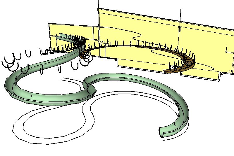
I was told that the elevations were placed correctly in relation to the plan view of the slide. The elevation view doesn't really represent the slide shape correctly I think, it appears only to provide a "path", don't you think? Something doesn't sink up for me. For instance the outermost extreme edge of the slide at the bottom doesn't line up with the outermost extreme represented on the elevation view. I guess that would make sense if the elevation view is represeting only the path of the slide, but then it doesn't line up with the outermost extreme of the centre line of the waterslide either. I think there is missing info that I need but I have asked for it 3 times now and I get only a few lines cleaned up and nothing more.I've push pulled the profile from the eleveation view through a push pulled profile of the plan view, but I get nothing logical at the intersections. Any ideas on how to approach this
-
Yeah, that's why I took it on. I've got it a bit further along now. The push pull through each other is a good start. But once I push pull up from the plan view, I delete the outer wall thickness and end up with only the center plane. Then when I push pull the elevation view through it, it does a better job of lining up. But there is some "noodling" to do.
-
Bruce, try that at the other end. where the slide is at it lowest point.
-
Susan, Bruce: I may not be tracking your conversation so if this just repeats forgive me, doing the pushpull on both it seems to me to work pretty good...just that the res of the curves are getting in the way. Personally I wouldn't take it any further and just fake it from here.
Alan F. posted a little tut when I made one a few months ago (I'll look for it) which will do the trick I think.
EDIT: guess it wasn't a tut...still spot on! The thread link:
-
I'm not sure I understand the problem, but here's my interpretation. The result is a bit messy and the path needs manually fixing at the apexes, but it's a start.
Here's the link to the model
http://www.sketchucation.com/forums/scf/sas/Ga ... 2%5dJB.skp
![Waterslide[2] JB 1.jpg](/uploads/imported_attachments/9jsg_Waterslide2JB1.jpg)
-
Tom, I need a more detailed explanation about the Alt Move which is usually "autofold" What exactly did you auto Fold? Can you do a little tut pretty please?
Jackson, I have your solution, now how did you get there. You couldn't use follow me so what did you use. -
Susan,
I pushpulled the elevation path through the plan path (just the centre line) and intersected them. Then I deleted everything apart from the intersection, did some manual intersecting at the apexes (SU's faceting meant the paths missed by a couple of inches) and just used followme for the profile along the path. Obviously using followme has resulted in the profile twisting a bit- most noticably in the middle. That why I left the path in my skp, so you can clean it up/smooth it out if you need better results. Hope this helped.
Bruce,
Sorry to hear that, but please note the dislaimer below.


-
When you create something from your imagination or from a photo, you can ensure that segments are a consistent length and otherwise simplify the project. Because of the different segmentation of the plan and elevation views and because of the nature of the curve, the segments of the path are all different lenghs, so a single component will not easily fit all around. Bummer.
-
Susan,
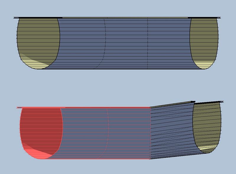
No time today for a proper tut but here's what so far:made a face of the section
followme
erase face junk
grabbed red stuff to autofold (I start with everything and remove as I go)...my slide's vertical displacement per section was about 2"
pull down the next bunch
pull down the last, then grab the center section
copy and group
copy rotate along the original plan curve
finally just moved each to connect up...tadaYou'll have to do same for each diameter of slide (but I'm betting they're really all the same mold even if their drawings don't show so...?)
After mine was built I scaled the whole thing along blue axis a bit to line it up with the stair tower ('cause I didn't type in enough decimals for the vertical displacement)
Hope this is some help, will check tonite.

-
All of these are great ideas to help along the way, but none of them work outright because of the way these have come in from AutoCAD and how the not matching segmentation.
For instance, I found the centers of 7 distinct attached arcs that were used to describe the plan view shape. Each of those were cut into segements of 12 but the segment sizes were different for each of the distinct arcs. Therefore there would need to be 7 different components. However. the segmentation of the elevation view is different and none matching and not correctly accounting for perspective so we all agree there was a fudge factor. Even without the fudge factor the resulting path from the intersect with model just does not directly match the segmentation of the plan view path. Therefore the components once angled would still not sit in the correct space/length for the path. I tried a number of different things.
I thought to place the copy rotated grouped ribs at each segment above the sloping undulating path and the tried to use the "drop.rb" to make them drop to meet the path below. Drop won't work with just a segment. Scratch that. I tried push pulling the elevation view profile again and using drop.rb so that there is a surface to drop on and then see if I can correct the ones that are on the overlap. No good. I think it is because of the difference in the segmentation, but at any rate it wasn't stopping at the bottom vertex of the profile, it would stop at varying place along the side of the profile. So I tried to move them into place manually starting with the lowest one and again, I ran into the problem that when you move straight down in the blue axis, the segmentation just isn't the same and things don't meet at center.
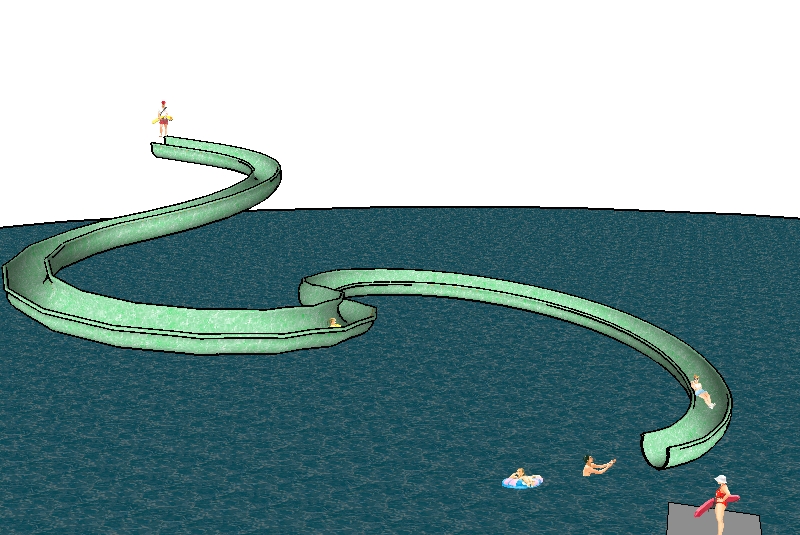
I tried a just plain follow me to see what I would get. Some of the lins need to be hidden because softening isn't enoug on them. But I have to say that it doen's look too bad other wise. I've been on these things and if I recall correctly, the opening is not always straight up. It does curve with the curve. What do you think? Is this good enough or will someone look at this and say no way. can't be right? To get this so that the opening is always facing up would require an enormous amount of work and fiddling. There aren't too many shortcuts available with this one.
I attach a jpg. No matter how I cut it down, the skp is too big.
I've also attached a jpg of one where the bad segments have been hidden and some people added for scale and context. I assure you the people are at a correct scale and I imported this accroding to the units given me for the ACAD file, so the slide really is very large.


-
I am reading this with interest, and your techniques are way over my head. I have helped in the construction of one of these slides, though it wasn't a water slide. On this one, the slider (or is it the slidee?) rode a little four wheeled car down the track. As you can imagine a lot of speed was possible, and to keep the rider from being thrown out of the track, the outside radius of the curves is the raised side. In other words, the opening is not square with the world, but instead curves in such a manner that the "centrifugal" force tries to push you through the bottom of the track. As you round a radius, you raise up vertically into the side of the track, so in effect the side of the track becomes the surface the car is riding upon.
I'm not sure if this helps, or if I have offended by pointing out something everyone already is aware of.
I am just mentioning this as the sketch shows the opposite, wherein the inside radius appears to be higher than the outside.
best
rollin' -
Actually, that is very helpful.Thank you. It confrims what I thought I rememebered about these. The opening is not always parallel with the ground. That is good to know. Thanks again.
-
Susan...cont:
took the curves of one side of your slide
found the center of each segment so I had the radius and the included angle of each
redrew the plan using radii to the nearest foot and angles to the nearest multiple of 15deg (using circles with 24 sides each...so each segment was again 15deg)
copied the new curve and offset 24" and 48"Now I have a plan that will work with the previous "tut". You may want to change the angle to 7.5deg for smoother slide...? What ever you decide on the number of segments (including any "straight" sections at top and bottom), divide the total drop by the number of segments to get the autofold offset. (If you think some sections slope more or less...adjust the offset accordingly.)
Hope this helps to clarify.

-
So kind of you Tom to continue the explanation. As I said, I did try that as well, but there were far too many components that then needed to be rotated to the appropriate sloped angle, far too many too lift into place because the slope was inconsistent and a copy rotate was just not possible and then the segmentation did not match the segmentation of the elevation view, they were segmented differently. It would have been different if I had created the plan and elevation views to carefully match. This was not the case. Another vote for planning things in SketchUp rather than AutoCAD.
Thank you again Tom. Didn't you say something about an "alt Move" though in your eplanation on the thread with Alan?
-
Yeah...alt-move is how I "autofold", or am I using the wrong term? By pressing the alt key during a move the faces compliantly triangulate to accommodate my desires :`)
If you select a curve (that has been arbitrarily segmented by SU from the autocad import arc) you can change the number of segments to suit your needs in the "entity info" toolbar.
As per creating the 6 components and correctly placing 45 of them to form your slide...ah well, such is life: time and money, or is it love.
-
Well, I know about how auto fold works, I just couldn't figure out where in the process you need the auto fold? Still can't quite figure out where you would use it?
PS> way more than 45 components. Something in the order of 7 x12 = 84 plus another 4 or 5 I think. 7 different arcs each with 12 segments. all needing to be rotated on a slightly different angle before being lifted in postion. then they would all need to be stitched in postion. Not a good use of time to my way of thinking. Wouldn't want to pay one of my employees to do it. Unless it was for a shop drawing I guess, but then I would have started with something a little more accruate from AutoCAD or whatever I guess.
-
Sorry Susan, I obviously wasn't explaining myself very well so gave an hour of my Sunday toward good Karma (least I could do :`)
Here's the your slide based on the simplified plan I described in my last post attachment. It's not exact, of course, and still could use a little adjustment...but close enough I think.

-
Oh yeah,
I use autofold to get from the upper to the lower...on yours (since it never crossed itself I just followme'd the whole path rather than making the 15deg components as described earlier) did same as below 46 times.

-
Doh, I understand now. thanks so very much. Of course, it is totally obvious when someone else has thought of it. Thanks again.
Advertisement


