Adjusting Terrain in the Real World
-
Hi All,
Got a query that's been driving me nuts! This is the second time I've done a model like this and I need to get a better understanding or technique on how to achieve what I'm after.
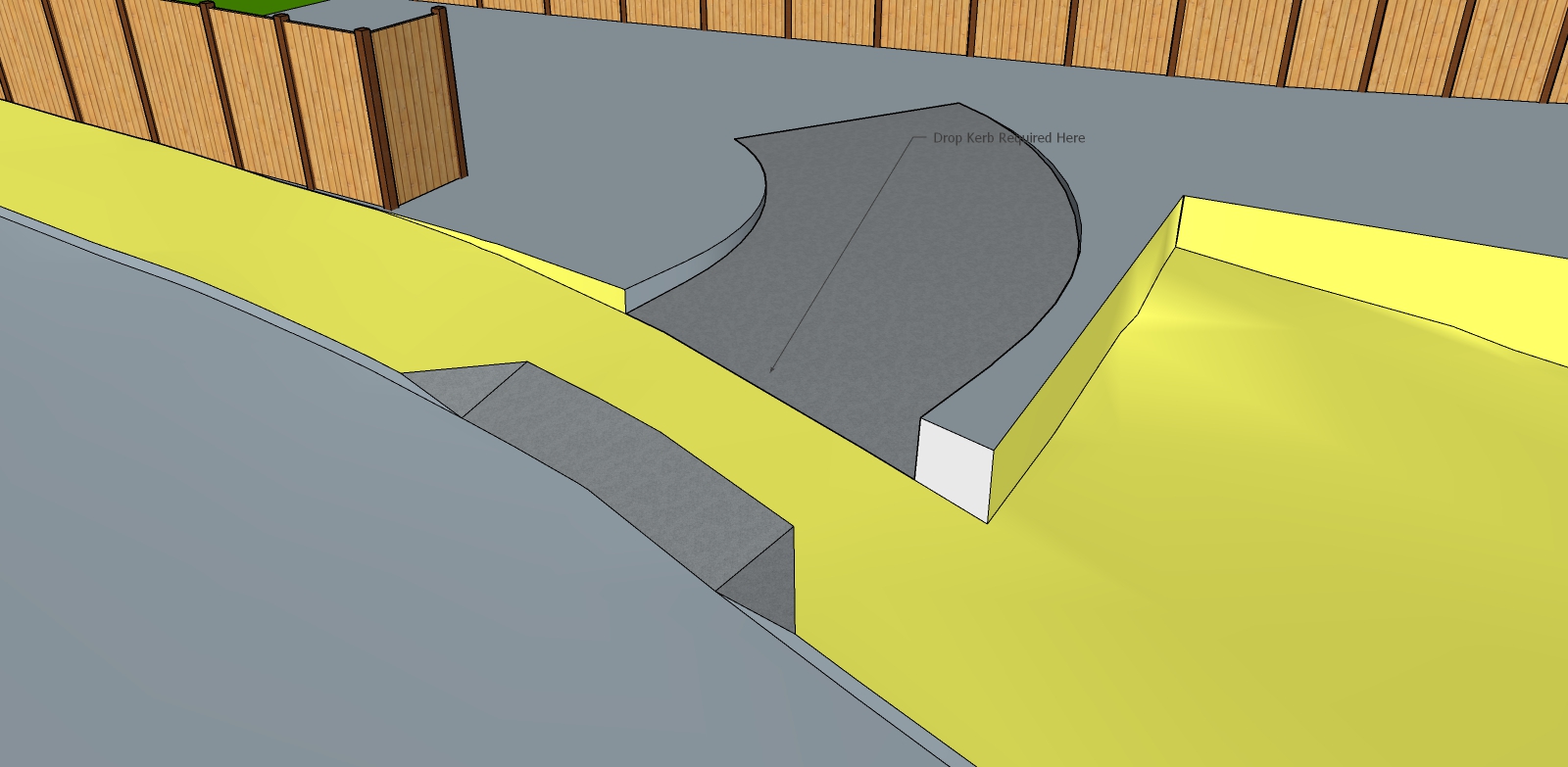
In summary I am taking terrain information from Geo-location and then placing a model of a new building in to it. In addition I add existing details such as roads, pavements, and some existing houses/buildings. My issue is in trying to alter the existing terrain to incorporate the required alterations to accommodate the new build. Things such as a flat pad, dropped kerbs or paths or, like in my latest model, a new garden area that follows the slope of the existing terrain but is flattened out. I have tried the stamp tool which is ok for creating a flat pad for the building to sit on but I've yet to find a way to use it that lets me apply sloping paths etc. Also, I have found this technique to be a bit limiting as later adjustments to the terrain created, can alter the flat pad, as they are all connected. Adjustment, as far as I can see is either by use of a circular tool, not always ideal, or moving parts of a triangle. All very imprecise. My latest attempt has seen me not using the stamp tool but instead creating a solid of the plot, including the sloping garden, and then inserting this 'through' the terrain. However, I still get the issue of trying to adjust the terrain to the positions I require. The adjustment tools just don't seem to have the control needed. I suppose in a way I need to be able to add in flat or shaped geometry to the terrain but don't know how to do it.
I would add, I have tried using Vali Architects tools for these operations and whilst they are some good scripts, they don't appear to me to be controllable enough. They're fine if you're modelling a new American style huge house in a wide open space, and you work to American building techniques such as grading etc, but if you're doing a small new build placed in to an existing congested urban environment, I for one can't seem to get the results I'm after.
I have also found it difficult to sculpt the terrain as it is clearly made up off lots of curved surfaces. So the usual push pull and using shapes to 'cut out' doesn't work. I have tried using JointPushPull but with mixed results.
I do concede that my woes may well be down to a lack of understanding on how some of this works, but I am open to guidance and would very much welcome peoples comments or experiences.
I will endeavour to upload a couple of models to hopefully help show what I'm on about. Regards.
-
That's quite a summary! I find that a lot of modeling both of graded and hardscape (paths) is easier to model using basic tools and as simple a surface as possible, then moving on with SoapSkinBublle, Curviloft and other tools for complex surfaces. Keeping the new grading work or the existing hardscape apart from the existing graded terrains and lesser "smoove" type manipulations of terrain (with Artisan often and vertex tools). This is when I am working with known heights and a specific design rather than just making hillocks etc. for a concept.
Where I need to work with a Toposhaper mesh I try to respect the geometry and avoid creating cut-up or poor geometry. Most accuracy for my models concerns wall and slab heights. (We usually have civil engineers and excavators on site who fine tune the rest--so your needs may vary.)
In your test file. On one hand you can leave the terrain combined with the hardscape as you have it Select only the main grading part not the verticals or parking lot. Use the Artisan scuplt tool set to flat and work that area down that needs flattening. It will pull down the bottom edge of the vertical parts with it.
On the other hand I would usually draw the vertical walls separate from the soil terrain as they would be built and are often simple constructions and avoid the "odd results" from manipulating complex (but originally very regular) terrain objects with complex actions. If indeed this is a concrete construction, this means you could add the below grade work if you wanted.
What's a dropped kerb? Again if you are initiating your new work with simple shapes as it would be made in the field (with formwork and lasers) adding simple features is easier than starting with an smoothed shape. You may wish to define your perimeter and after you've got the edge points accurate, use SSB or other plugins to fill-in difficult surfaces.
-
Hi PB,
Thanks for the reply. I can't begin to claim I understand all that you've said there though. Certainly I can relate to modelling in simple shapes as much as possible and have tried that. However, I very quickly get to the point where the shapes required become too complex. I have never attempted any organic shape modelling at all.
You've certainly mentioned some extensions that I was not aware of so I will be taking a look at those, thanks.
Sorry, UK terminology there. A dropped kerb is where the pavement (sidewalk) has a slope created from road level up to the driveway of a property to allow vehicles to drive on to without have to 'bump' up the kerb. I guess in the US you'd just call it part of the drive. Creating that slope as a new feature from the slab to join with the existing road, which is also sloping away in another direction, has proved to be particularly tricky
-
Yes, probably no simple solution to that driveway unless some plugin master has figured it out. I suppose advanced civil engineering software may have a routine. Makes sense, "dropped kerb". We might call that a "curb cut", though that's not very descriptive.
I think for the small site you'd just assume the grade changes all around with a vertical surface, whether that is a retaining wall, a small transition at a fence, or a couple cm at a kerb or sidewalk. Then the onsite surfaces can be less complex, don't have to meet the existing terrain point for point, as they abut a vertical plane.
-
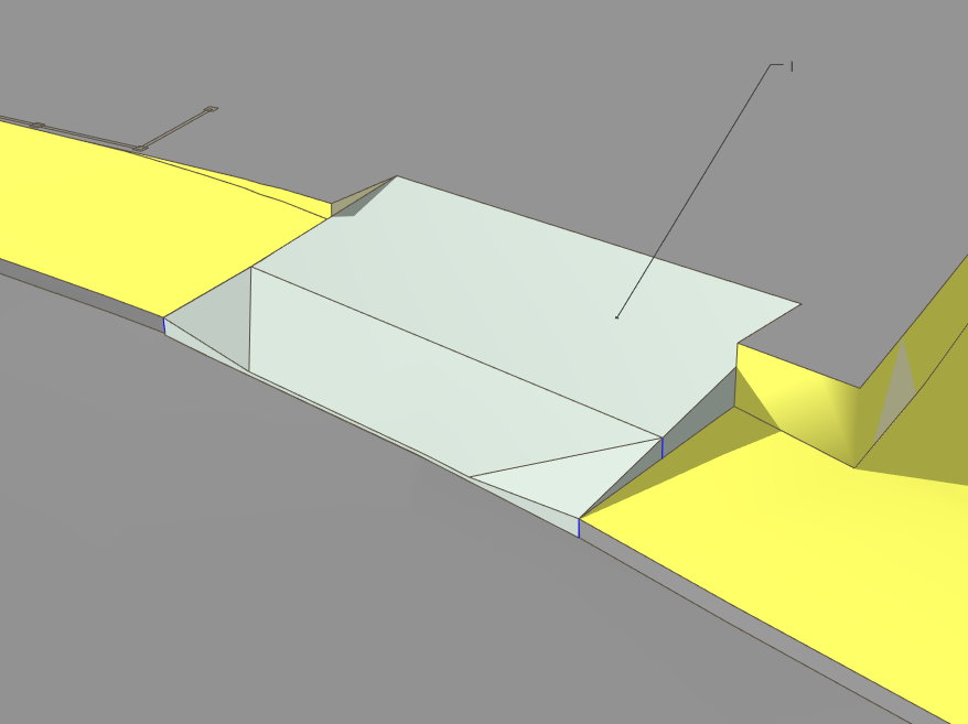
So here's a try to demonstrate my idea. I just drew a rectangle and push pulled it to through everything in the area I wanted the dropped kerb. Then used intersect faces on the terrain.
I don't know, of course, the desire or the constraints on how you were hoping to make this.
I decided I would tell the builder he can cut a straight line along the road as it is not that far off. there's going to be a lip there. I started by establishing a line at the kerb and building a vertical face from this line, and push pull a box back into the platform. I used this box to cut the terrain.
The box was the start for my front kerb face of the driveway and the sides. Removed the parts of the box above that I didn't need. Then I could draw the surface up to the platform.
(this was my second try after I realized how to use the box correctly!) The box and the driveway are grouped separately from the terrain all along.This could apply similarly with flaring the sloped sections to the sides instead of inward. Add the flares to the box shape first.
Terrain Testing (original) 4.skp

-
Hi Again and thanks for the reply.
Thanks for taking the trouble to actually model a solution. You certainly have got a lot closer than I did. I have tried to recreate what you have done but I'm not getting the same results. I must admit I don't really use Intersect Faces preferring instead to use the subtract, trim etc tools to cut and add to shapes. I suppose that is part of my problem, as the terrain does not act as a solid?
From what I understand of your explanation you've created a box and then intersected it with the terrain. Did you then manipulate the lines of that box afterwards to make the shape you have?
Unfortunately I can't open the file that you have created as I use SU18 and your file is 19, so I can't take a closer look at what you've done.
-
Adding to and echoing pbacot's excellent advices, I hope this might also be of use.
I would stick with the native SU tools and get a thorough grip on what can be done with them. Have a look at some of the YouTube videos; Justin Geis's TheSketchupEssentials has a lot of good information.
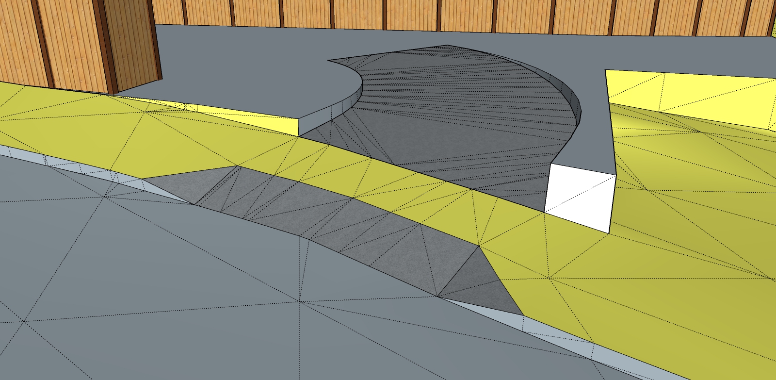
There are, of course, many different approaches to terrain modelling but with the Sandbox tools in mind, using a combination of these could help rather than using just the one tool. Definitely keep your building footprint and hard landscape as separate groups or components. I have done some work on your original SKP and hope that it will be more illuminating than what would be a rambling commentary on what I did! Essentially, I drew the required outlines on a flat surface above the model and used the Drape tool to indicate where to cut into the terrain and re-build with the drop curb and sloped driveway. If you would like to PM me I will try and answer any queries.


Advertisement


