Medeek Wall Plugin
-
I think the key issue with which I am trying to address with this new tool is best summed up when you compare SketchUp (SU) with Chief Architect (CA). Both can be used to model a structure, one is fully parametric but is quite locked down and restrictive while the other is very free form, allowing the user to do as they please. The downside to this freedom is that the program has no way of keeping track or making sense of all these custom changes and hence the parametric ability cannot natively exist.
CA does a nice job of keeping everything well contained but its 3D environment locks the user down too much in my opinion, and for the designer (who is not too different from an artist) who wants to express their creativity, I think this can be too restrictive.
Being able to insert "custom" geometry into the wall, roof and foundation assemblies, whilst categorizing and tracking it maintains the parametrics (and estimating) but also allows flexibility. Being able to retain this custom geometry after a regen is critical to the success of this paradigm.
In a nutshell the plugin is trying to maintain the flexibility of SU while giving the user the parametrics of a program like CA.
-
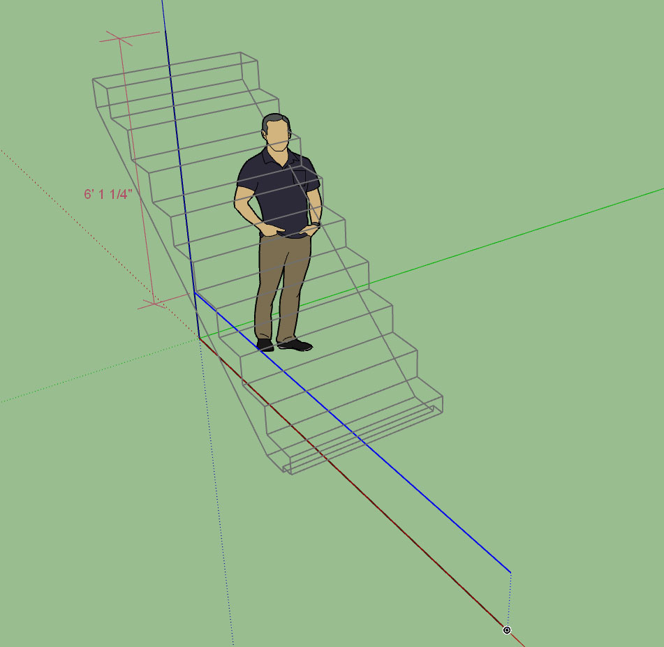
Running the stair module through a few tests this evening, found one minor bug and was fairly pleased with the stair envelope for checking headroom height:
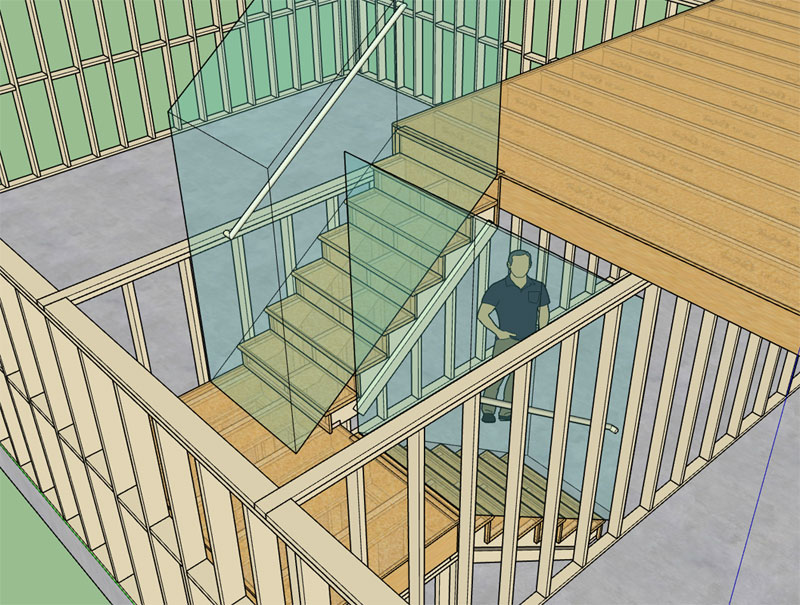
I've also added one additional termination (OTP with a 2 riser gooseneck) which is typically used where you go from one flight of stairs to the next as show below:
As long as the riser heights match (like they should) for each run of stairs then the 2 riser goosenecks matches up perfectly with the starting ease of the next run of stairs. Of course the specified hand rail height for each run must match as well.
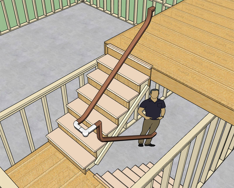
Note that the white color (handrail fittings) components are not being automatically generated by the plugin those were manually inserted, however the brown sections of handrail are automatically generated and they matched up perfectly as expected (Z height). I left the fittings white so you can see what elements were required to be brought into the model.
These fittings will be included with the plugin in the library/handrail_fittings subfolder. If I get ambitious I may have to actually model up some volutes for the bottom of the handrail but for now the list of supplied fittings (for the LJ6010 profile) is:
- S7011 (right handed)
- S7019
- S7020
- S7021 (right handed)
You'll also notice that in the top image I've created a landing with a 2x4 pony wall supporting it (sorry barely visible). When you go to create walls like this it would be nice to have the plugin ignore any surrounding walls and basically treat these walls as completely isolated from the rest of the structure.
With that in mind I reworked the auto-corner configuration algorithm ever so slightly, so that it is now possible to place any number of wall panels within an over arching group. What this does is effectively isolate these walls from any other groups within the model.
I will need to make some updates to the estimating module so that it is smart enough to look for groups in the root of the document with embedded walls. I will also need to make a video demonstrating this technique, and when and where it would be useful.
Granted, I have not extensively tested out this new feature so I would say proceed with caution but my preliminary testing shows that it is quite effective and convenient when modeling sub-assemblies within a larger context.
-
Version 0.9.9r - 12.05.2018
- Added a "2 riser gooseneck" Over-the-Post termination option for all handrail profiles.
- Adjusted the auto-corner configuration algorithm so that wall panels can be placed within larger groups within the root of the model (wall panel isolation).
- Fixed a bug in the Over-the-Post section of the handrail/stair module.
-
Here is a quote from a review of Nick Sonder's book on Amazon that parallels some of my own thinking. The reviewer first touched on his use of the book but his final remarks regarding SketchUp and design work really hits home:
@unknownuser said:
This books has a lot of different tips when working with SketchUP. But I have to say, after going through many weeks thinking I was able to use this for production drawings I was sadly mistaken. By time I was able to get everything exported out to Layout, the drawings just did not look good at all. The resolution was way too grainy for my liking. The vector overlay was too bulky and raster was too pixelated. I am sure there is a way to fix this, however the next part made me re-think the whole process. Layout was so slow to regenerate the image. Each time I would pan it would pulse the screen and my workstation grade computer was just not able to do what Layout was requesting of it. My computer and workstation graphics card is not by any stretch old or limited. The thing runs all other software great. This was a huge disappointment...
All around if you are thinking about transition from your existing software to Sketchup Layout I would recommend some hesitation. However, if you want to learn a decent way of putting a Sketchup model together, I do recommend the author's techniques. I still use them for normal Sketchup use, I just cannot see investing in the time and patience with regards to Layout work. If someone is thinking of transitioning it might be better to look at an actual BIM software and if you are like me Chief Architect seems much more appropriate. I want to love this, because I think Sketchup is by far the most flexible software when it comes to heads up design. You are not stuck in dialog boxes, which for design flow and immersing yourself in the architecture SketchUP is great. I wish Trimble would take a few notes from a software like Chief Architect and simply some of their rules and plop them into Sketchup. I also think if Sketchup spent more time thinking how Architects might use Layout as full production drawings would be great, you really should not have to go through some of these crazy steps to get great drawings from SKUP. It's just not quite there, and this process does not make it that much smoother.
I'm not wanting to disparage Nick Sonder's work or his workflow, I think out of anyone his is some of the best. My concern is with Layout and SketchUp itself as an architectural tool. I feel like the plugins are starting to bridge the gap or parametric edge that Chief Architect has had over SketchUp (with a fair distance to go yet). However, the other area we are falling down in is the creation of construction drawings and documents.
I am excited to start work on the automation of this piece of the puzzle and really dig into the Layout API, however at the same time I am genuinely concerned with Layout itself, and how well it functions as the 2D engine underneath the hood. SketchUp's recent updates to Layout in the last two years/iterations have been tepid at best. We really need a solid 2D drawing environment, something that can go toe-to-toe with AutoCAD. I realize that this is a big ask, but it needs to happen.
I've already invested a considerable amount of my time into developing these plugins and I will continue to invest more. I've been full time at it since April of this year and rather than work a salary man's job I chose to pursue this much more interesting path (we will see whether this was foolish on my part in the months to come).
As I continue to develop these plugins I think it will not only benefit myself and the designers who use the software but also SketchUp itself as more architects, engineers, designers, contractors and draftsmen are able to utilize SketchUp as their primary design tool. The work I do, as well as others like PlusSpec and John Brock to name a few, is helping put SketchUp on the map in the architectural design world. We are helping pull users of other design software, such as Revit and Chief Architect, and converting them to SU. We are trying to do our part.
It is now up to SketchUp to boost the Layout development and do their part. We need a world class 2D engine. Without it, we can't compete, it doesn't matter how good my 3D models are, they have to translate into construction documents, and it has to be seamless and effortless and a joy to use. Unless Layout is brought up to par I will be forced to go alternative routes such as exporting floor plans to DXF etc... This is really not the route I want to go but right now I am seriously considering it.
-
Hi Nat,
I haven't attempted what Nick does,(but I did buy his book right off the bat). I generally run my building elevations through LayOut directly to pdfs in PowerCADD and finish drawings and notes there (the graphics, text, and CAD tools are so far beyond LayOut to ignore) Still Nick's work looks great (in contradiction to the review)and he does it somehow without going crazy from the slowness. I do agree LayOut is very slow, and Hybrid at highest quality is the only way to go, yet produces heavy pdfs (Mac print to pdf). The reviewer didn't mention that working in LO at a lower resolution is quite OK, to avoid slow performance, even though output is going to be slow. Just hoping it's going to be better. I think the reviewer would be interested in your plugins, if he likes Chief Architect.
Peter
-
@pbacot said:
Hi Nat,
I generally run my building elevations through LayOut directly to pdfs in PowerCADD and finish drawings and notes there
Peter
How exactly are you getting your drawings from Layout into PowerCADD? What file format (PDF)? Vector data I'm assuming.
-
I'm adding two extra parameters which will allow an extension of the bottom of the stringer as shown in the detail below:
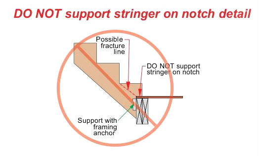
This detail was taken from literature for LVL stringers. Notice the use of framing anchors to help bear some of the vertical load.
I prefer to extend the landing back to catch the full bearing of the stringer but I guess there are some situations where additional headroom is needed or other configurations where this method of stringer support is optimal.
-
@medeek said:
@pbacot said:
Hi Nat,
I generally run my building elevations through LayOut directly to pdfs in PowerCADD and finish drawings and notes there
Peter
How exactly are you getting your drawings from Layout into PowerCADD? What file format (PDF)? Vector data I'm assuming.
Generally I am just using thr pdf image and drawing over it in scale and adding notes. If I need to snap (or get edges) I can import dwg or an exploded version of the vector pdf and place it behind the image. Sometimes I do use the linework itself without the pdf.
I found a way to print all the LayOut pages to pdf with names "house page 1, house page 2" etc.) in one operation. I reference the pdf file in PowerCADD (instead of importing) and they update if I save new pdfs.
-
First look at the stringer extend option with its associated notch:
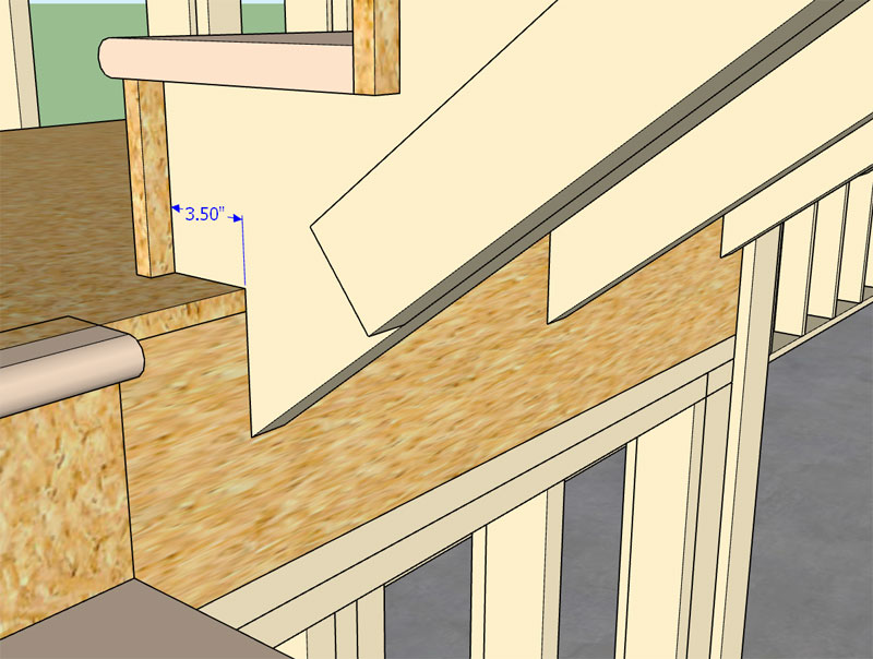
You can also enable the thrust block with the extension/notch but I don't really see the point to doing that, it only further weakens the stringer at its point of bearing.
I'm thinking I should probably extend the side spacer down all the way until it meets the landing/notch, unless there is a good reason not to.
Also I've been reviewing all of the html menus and there are quite a few places where I am displaying
or requiring input in inches and it would be nice to also display the same dimension in ft-in. (fractional), I am looking at this now. -
Version 0.9.9s - 12.06.2018
- Added two parameters in the stair module to allow for extended stair stringers.
- Draw and Edit Wall menus now display wall height in feet and inches (fractional) when using an imperial units template.
- Added the action: "Regen Wall Assembly" in the context menu for all wall assemblies.
I've also gone ahead and enabled the feet-inches dimensions for other applicable dimensions within the global settings tabs (Walls, Door, Windows, Stairs).
-
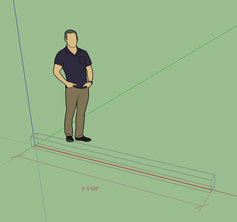
Here is a first look at the updated draw wall tool with a temporary dimension enabled:
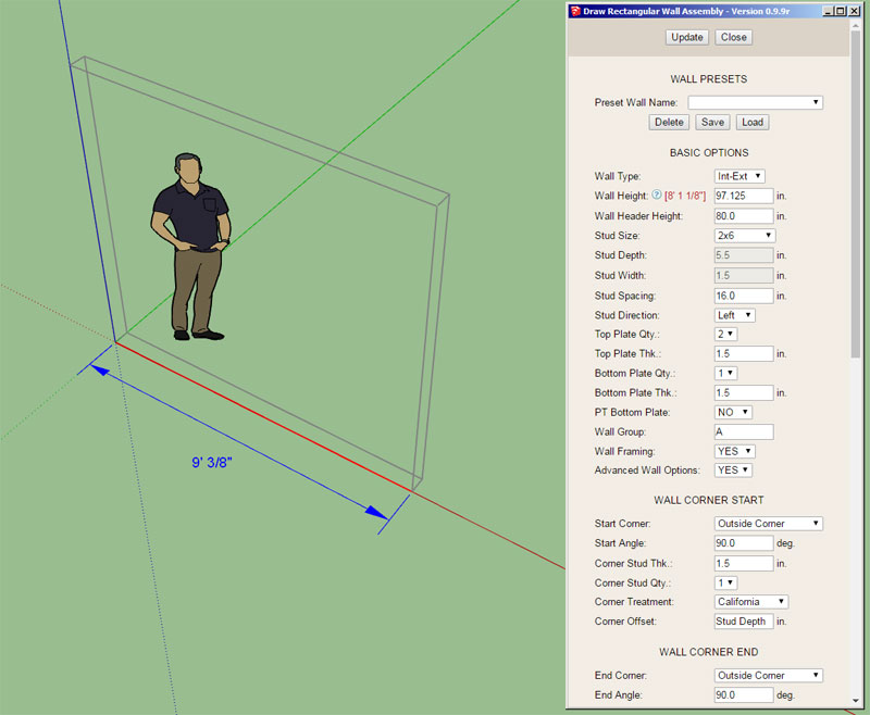
I think it came out alright, however I can change up a number of parameters to improve the aesthetics if there is call for it. The parameters for the temp. dimension currently are:
Extension Line: 18"
Dim Line: 12"
Ext. Line Offset: 1.5"
Dim Color: 0000FF
Text Color: 0000FF
Text Size: 14pt
Text Font: Arial
Arrow Width: 3"
Arrow Length: 7"
Line Weight/Width: 1 -
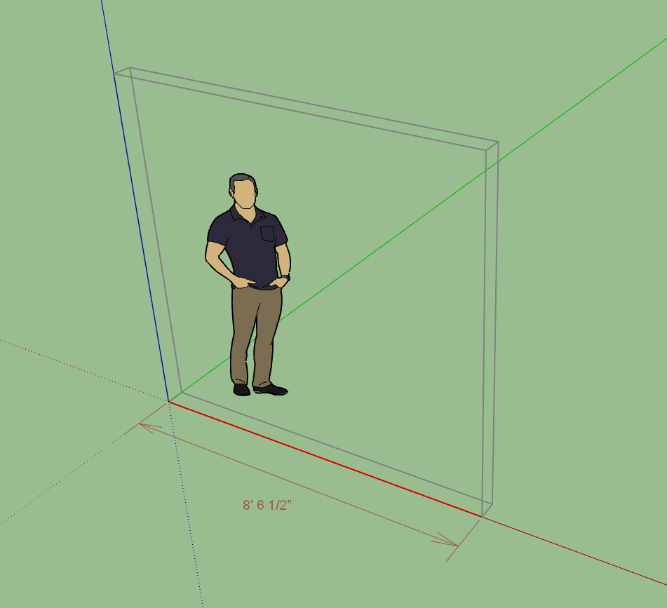
For now I'll go with: rgb #447088
https://www.color-hex.com/color/447088
It's kind of a muted green-blue. Eventually I will make the color configurable for the user.
-
@medeek said:
I can change up a number of parameters to improve the aesthetics if there is call for it.
I have to say that (as an architect
 ) i don't really like those arrows. I would prefer strokes. And the text aligned to the dimension line, like in Revit for example... https://youtu.be/hdgyZd_EiD4?t=89
I really enjoy watching your progress in this thread!
 It would be great if Trimble would show only a fraction of this speed and transparency in their development.
I think you're doing a great job and i really would like to buy your wall plugin, but for my work it's too specific and limited. The design of the wall features and components doesn't fit my work and i think I would need a more flexible and customizable approach regarding doors, windows and stairs, like custom components.
I know it would be a completely different thing and much more elaborate, but it would be great if there would be some kind of parametric component like in Revit or Acad. I don't know if this would be possible as a plugin, but maybe this could be developed as a separate plugin for parametric components in general and then linked to the door/window function... just dreaming -
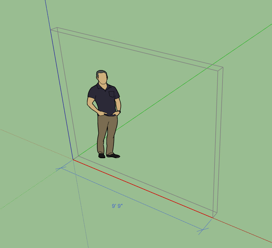
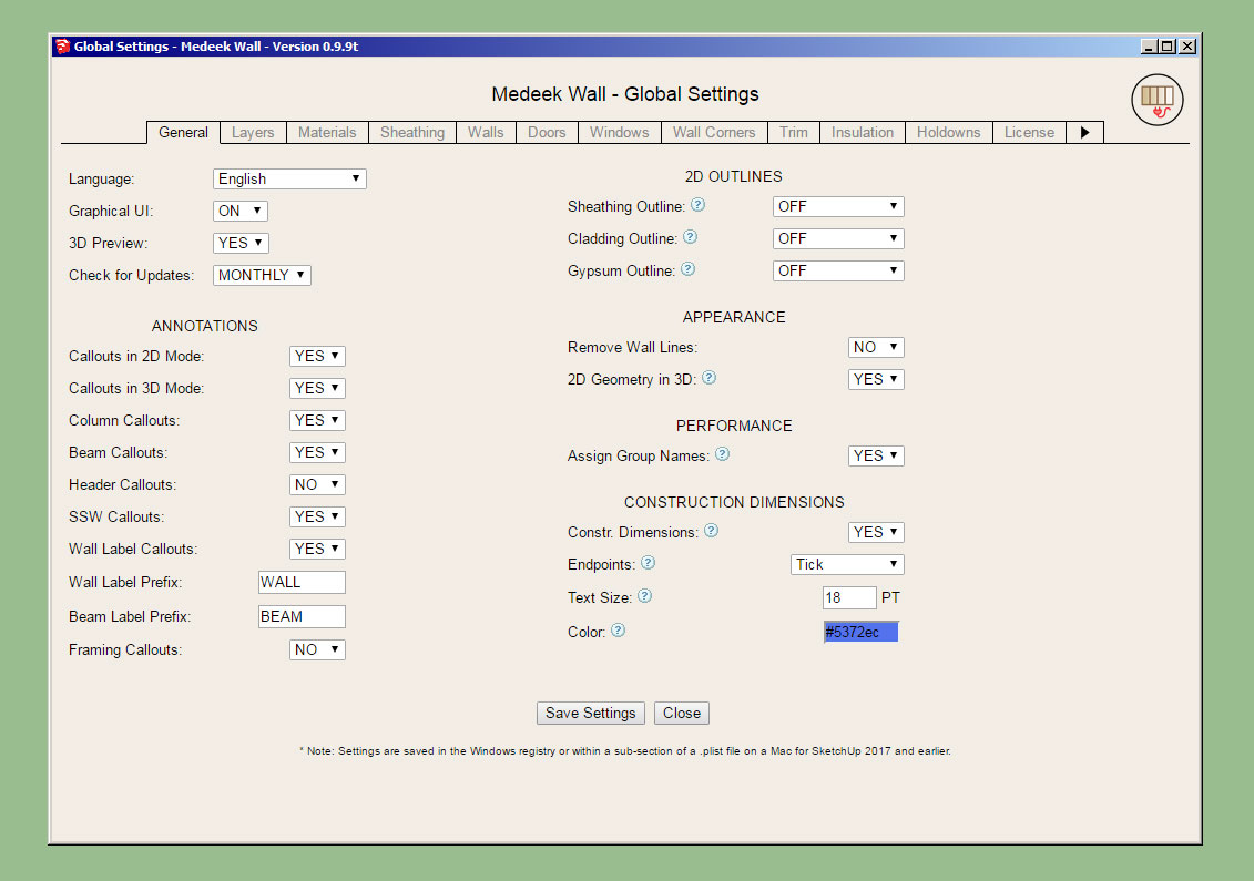
What I really need to do is enable some additional options in the global settings for construction dimensions:
Color: RGB value
Endpoints: Closed Arrow / Tick
Text Size: 14 Pts default
Also the ability to enable or disable them.
The color will also apply to other temporary dimensions and graphics utilized in the wall move and opening move tools, as well as the upcoming stretch wall tool.
I think it is imperative that I allow the user to set the color so that they can find an appropriate color to work well in their particular style. It would be very bad if the dimension color and the background color were too close and the user could not distinguish between them.
-
Version 0.9.9t - 12.09.2018
- Enabled temporary (construction) dimensions for wall panels in the Draw Wall tool.
- Added a section in the General tab of the global settings for configuring construction dimensions.
I've also added the option for closed arrows, open arrows and ticks:
Note the larger text size set to 18PT versus 14PT in the previous to screenshots:
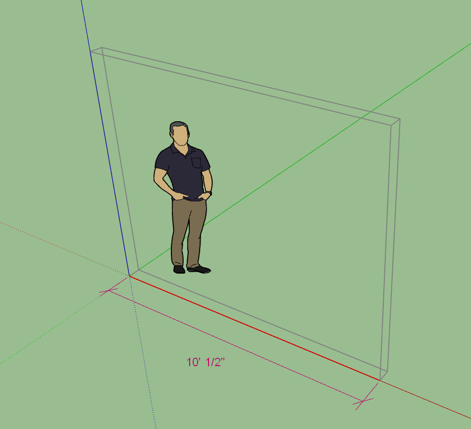
The endpoint, color and text size of the dimensions can be configured in the General tab of the global settings:
Hopefully this is flexible enough for most users. Alternatively you can also turn off the construction dimensions if you would rather not have them displayed.
-
Figured I might as well add construction dimensions to the beam and stair modules:
-
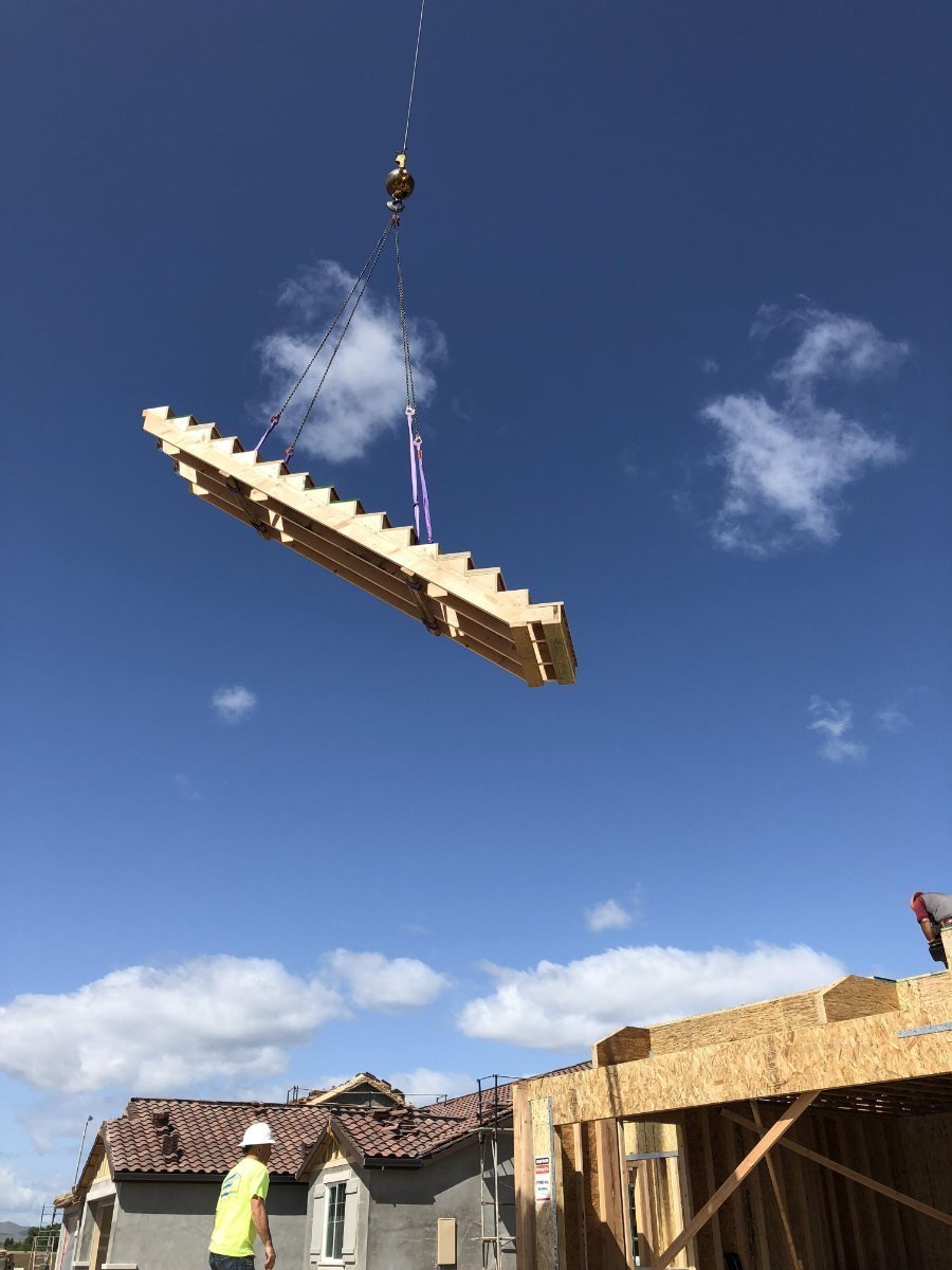
Now this is the way to install stairs:
-
Tutorial 7 - Stairs (23:19 min.)
Unfortunately there is just too much information to convey regarding this new module and the video doesn't really dive deep enough into all of the details and options, but hopefully this will be enough of a primer for getting started with stairs.
I also discuss the new wall isolation concept in some detail in this video.
-
For CMU I actually use two textures/materials to simulate the look and feel of CMU brick. One for the vertical faces and one for the faces normal to the vertical (horizontal faces). I could add a couple parameters in the materials tab of the global settings which allows the user to select their own material for these two face orientations for the CMU framing option.
-
As many of you know I am currently programming the plugins full time (ie. its my only income). As such my wife and I sat down yesterday to review the progress made on the plugins in the last year and our prospects moving forward into 2019. As I have previously mentioned I will be re-assessing my pricing and licensing as we bring the Wall plugin out of BETA.
As much as I detest subscription licensing that seems to be the direction I need to be going otherwise I will not be able to keep working on the plugins full time. I am not a huge fan of any form of subscription licensing, I prefer to BUY a product not lease or rent it. This is why I have remained at odds with going to this form of licensing even though it does make financial sense and would give me more stability and resources to continue further with the development.
I guess my biggest issue with subscription licensing is that if your subscription lapses then you are essentially locked out of any of your previous work/projects. I can totally understand the frustration with something like this, for many including myself it is a deal breaker.
After pondering this problem with this form of licensing it occurred to me that maybe one could set it up in such a way that all of the editing and misc. functionality of the plugin is retained even when the license has lapsed however the ability to draw new geometry (assemblies) would be limited. In other words you could still use the plugin to edit existing walls, beams, stairs, windows doors etc... However you would not be able to draw new elements or assemblies unless the license was active.
Let me know if such a compromise with regards to adopting subscription licensing would be acceptable.
Hello! It looks like you're interested in this conversation, but you don't have an account yet.
Getting fed up of having to scroll through the same posts each visit? When you register for an account, you'll always come back to exactly where you were before, and choose to be notified of new replies (either via email, or push notification). You'll also be able to save bookmarks and upvote posts to show your appreciation to other community members.
With your input, this post could be even better 💗
Register Login


Advertisement