Shape Bender Difficulties with A.C.M.E Thread
-
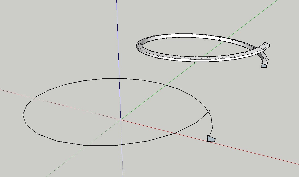
Hello guys, Hope someone out there can help or advise regarding the creation of a threaded shaft. I have only just installed Shape Bender Plugin and am using SketchUp 8 Pro. I saw a video on you tube which shows Bolt or Screw Threads in SketchUp with Shape Bender Plugin and I though perfect as I was unable to do this prior to installation. However the author does state that there are some minor bugs that he is currently working on. My situation is this. I wish to render a component that is a Shaft so a basic cylinder is easy but then i need to cut or form a thread around this shaft. Im a machinist so in the real world the thread is formed by cutting material away. Im encountering difficulties however.. I make an arc 5/8" of an inch in diameter.This is the diameter of the shaft in the real world. I lift one end of the arc 1/16th". I then Move Copy the arc before rotating the arc 180 degrees. I then move the copyed arc to the endpoint of the first arc and this forms the profile or outline of my first thread the Internal diameter of which is then 5/8" and the 'Pitch' (The distance between threads is then 1/16th x 2 = 1/8th". I am working from a Machinerys Handbook which gives charts and data tables for all types of mechanical components and is VERY accurate! Often to 5 decimal places so I have all the necessary information and tools to render mechanical components accurately. However when i then continue with the tutorial things start to go wrong. I create my thread profile, I extrude it 'Push/Pull' , I group the 'Model' I create a line for Shape Bender to use , I select the group, I click the shape bender icon, I select the straight edge underneath the group and then I select the helix or spiral that is formed from two arcs and finally I press enter and I get garbage EVERY TIME. I need to understand if SketchUp can in fact Draw Accurately or do I need to draw in x100 scale and then scale components down ? I am going to post 4 jpgs of the Results and procedure to help explain what is happennning. Please check the following links.
http://i265.photobucket.com/albums/ii219/GfxMan2008/ACMEThreadFailure1.jpg
http://i265.photobucket.com/albums/ii219/GfxMan2008/ACMEThreadFailure2.jpg
http://i265.photobucket.com/albums/ii219/GfxMan2008/ACMEThreadFailure3.jpg
http://i265.photobucket.com/albums/ii219/GfxMan2008/ACMEThreadFailure4.jpg -
OK Guys this is a short Update from this afternoons earlier post. I decided to work with what I had so using the line tool I created faces between the endpoints on each arc segment created by Shape Bender. This took AGES to do as certain faces were not flat so I simply ignored its inaccuracies and created extra vertices or edges using the line tool , thereby joining opposing corners of a rectangular face effectively splitting it into two triangles which formed individual faces but at least there was a surface in place. I then Copy Moved the entire thread and created a group but found that when I Copy Moved it to join the end of the previous thread that the outer and inner diameters were missalighned. So even if the two edges of the inner thread diameter did meet up when joining two threads the outer surface of the threads were not so it looked like a Chip had been removed from the thread. I moved the lines equal distances untill they met in the middle but this is a horraible approach and increases the inaccuracy of the model which is poor anyway. I think while SketchUp is a usefull application it fails in modelling small accurate components and is more suited to larger architectural projects. That combined with Shape Benders inherrent bugs make 3D modeling of machine components rather frustrating and inaccurate. Anyway Im going to upload a picture of the finished item. Im rather dissapointed by it at present so may redo it at some point in the future. Whether or not its using sketchup remains to be seen.

-
Hi Beginner123,
the simplest method is to do it with Follow Me and Keep ruby.
Charly
-
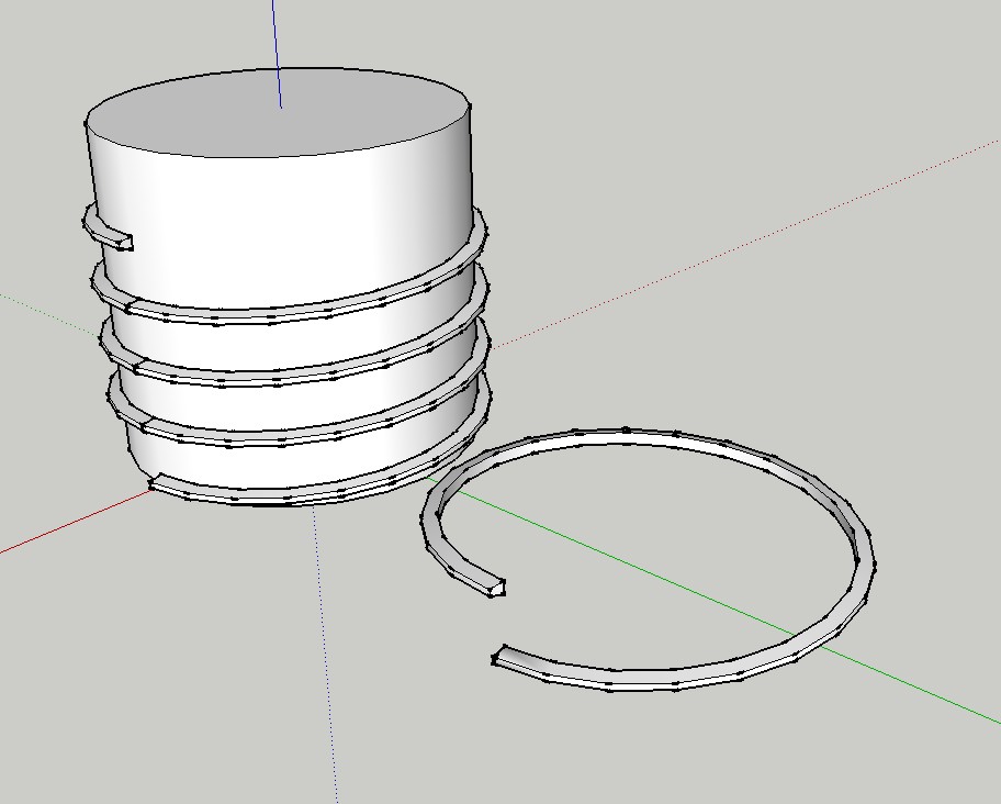
I would (and have) drawn acme threads differently. You might find it useful.

I made a component of part of the thread, lower right in the image below. Then I copied that to make a single turn of the thread and copied the turn to the desired length. This gives me the ability to create a screw of any length I need in seconds.

-
Take a look there.
http://forums.sketchucation.com/viewtopic.php?f=15&t=15784#p122571
Hello! It looks like you're interested in this conversation, but you don't have an account yet.
Getting fed up of having to scroll through the same posts each visit? When you register for an account, you'll always come back to exactly where you were before, and choose to be notified of new replies (either via email, or push notification). You'll also be able to save bookmarks and upvote posts to show your appreciation to other community members.
With your input, this post could be even better 💗
Register Login


Advertisement