Is it possible to offset a 3d spline?
-
I still don't get it. Have you tried the regular offset tool in SU? Does it do what you want? If not, what do you think should be different.
Chris
-
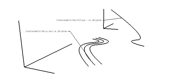
when you create a bezier spline - it usually does it based on a 2d axis constraint. I.E. it does it along the xy, yz, or xz axis - or along a constrained single face. However when you have a welded spline or a bezier spline that is oriented in xyz - i.e. a bezier spline that starts off of xy and then slowly goes into the z axis. Maybe a picture or a sketchup file will help.
-
How would you expect a 3D line like that to offset? Seeing how it flows in all three directions there's a number of ways it could be offset.
-
I tihnk what you are wanting is to just scale the spline. But it is a little tricky because you can't do a copy-scale link oyu can do with move. Sop take your spline, turn it into a group. THen copy and paste in place. The scale the new group. Then copy and paste in place again. And scale the new group again. See if that does what you have in mind.
Chris
-
@chris fullmer said:
I tihnk what you are wanting is to just scale the spline. But it is a little tricky because you can't do a copy-scale link oyu can do with move. Sop take your spline, turn it into a group. THen copy and paste in place. The scale the new group. Then copy and paste in place again. And scale the new group again. See if that does what you have in mind.
Chris
That won't work, as inner corner offsets will be smaller and outer will be larger.
-
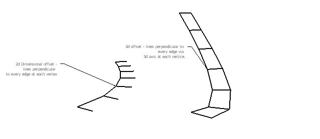
I think the best way to do it would be to have a line or construction line at the vertex between each bezier edge to guide the path for the new line. I.E to every vertex a perpendicular construction line would be created and then based on the distance guided by those construction lines connect the dots - and get an offseted line. I mean that is how it works with the tools on surface - except it already has a face. I think a picture will say it better than me.
-
I think the closest thing is TIG's grow script. One of the problems with the idea is that a single point doesn't have such thing as "perpendicular" in 3d space. So those endpoints are difficult to solve.
The tools on surface work so well because he isn't actually working on 3d space. His shapes are confined to the 2d of the faces they are working on, so there is a 3d constraint on them, making it possible to determine where they should go.
Something like what your asking might be possible to make, but the results would be VERY unreliable. Sometimes it might do what you want, and sometimes it won't. That's my take.
Chris
-
i know, what i meant to say a perpendicular line to each edge preceding the vertice that way it isn't constrained to 3d space. its like taking the follow me tool and using a square to follow the a constrained geometry - i.e. a square. The distance of the height and width of the square would determine where the offset line would go. Maybe like this? (p.s. the determining factor i used as the follow me constraint was your perpendicular face tool
 , which is really great)
-
Hey Chris, I just wanted to thank you for your help either way. Your tools are more than great, and i just wanted to show you I really appreciate your advice. Thanks a lot man.
-Sam
-
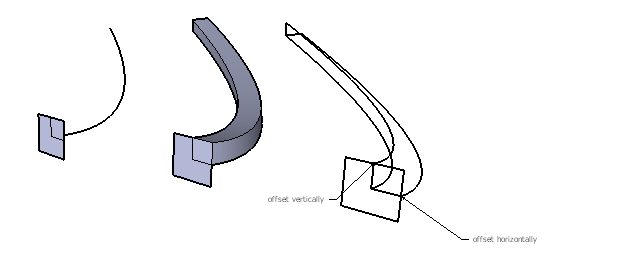
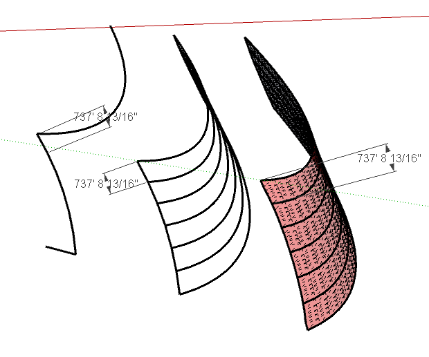
You could use "Follow Me And Keep" to extrude a rectangular profile and then delete all faces of the resulting object.
To delete all faces and keep only edges, change to wireframe mode, select everything with a marquee, cut it, return to shaded mode and paste it.
Here's a skippy showing the "before" and "after". If this is what you want to achieve, let me know and I'll explain it in more detail.
-
Yep, thats what i did in that image that i posted before the last one.
. I was just wondering if this can be automated. -
Yeah, I have a feeling that the follow me and keep method might be the best way to do that. Essentially the offset you are suggesting is one that ignores the z or blue axis. So when you offset it on the blue, there is no change. Its just like a copy. But on the red and green it expands like a true offset. I think you'll find in your example that the upper offset is no different than the original line.
Its not a bad idea, and with webdialogs it would be possible for the user to indicate which axis to ignore, making it possible to be more specific about how to get to the desired offset. I keep finding that webdialogs are the solution to lots of my UI issues. I need to learn those so it would be possible to create a script like this that lets the user supply more information about how they want the script to act.
Maybe Webdialogs are my next project.....that means learning me some javascript.
Chris
-
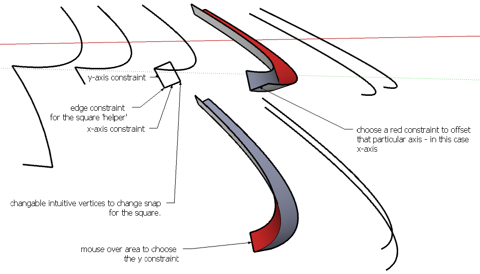
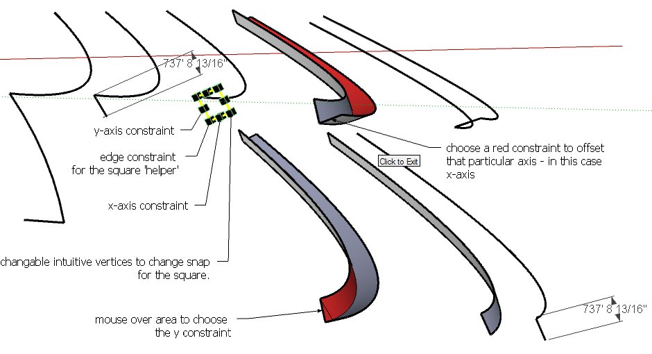
There is also a very interesting way to be able to control it intuitively without a web based dialogue. I don't know if this is possible if you were to create a small resizable square along the nearest vertex you click to offset the line and intuitively resize it or snap an edge to constrain the 'follow me' function and then simply offset the distance of that particular box along its edges. I'm always bad at explaining things, maybe i can show it in a picture once more. lol
-
Sorry guys, let me repost it with the snaps
.-Sam
-
Actually now that i think about it, it could be a new function for lathe - given if it can take every custom angled edge on the area that it follows and uses this offset tool to follow with for the lathe tool.
Don't mind me guys, i'm just dreaming. lol 
-Sam
-
You could try offset.rb
While I wrote it to provide standard "flat" offset capability, I noticed it does perform 3d offsets. It may not be exactly what you want, but it could form the basis for a 3d offset.
Hello! It looks like you're interested in this conversation, but you don't have an account yet.
Getting fed up of having to scroll through the same posts each visit? When you register for an account, you'll always come back to exactly where you were before, and choose to be notified of new replies (either via email, or push notification). You'll also be able to save bookmarks and upvote posts to show your appreciation to other community members.
With your input, this post could be even better 💗
Register Login


Advertisement