Line/Plane Intersection
-
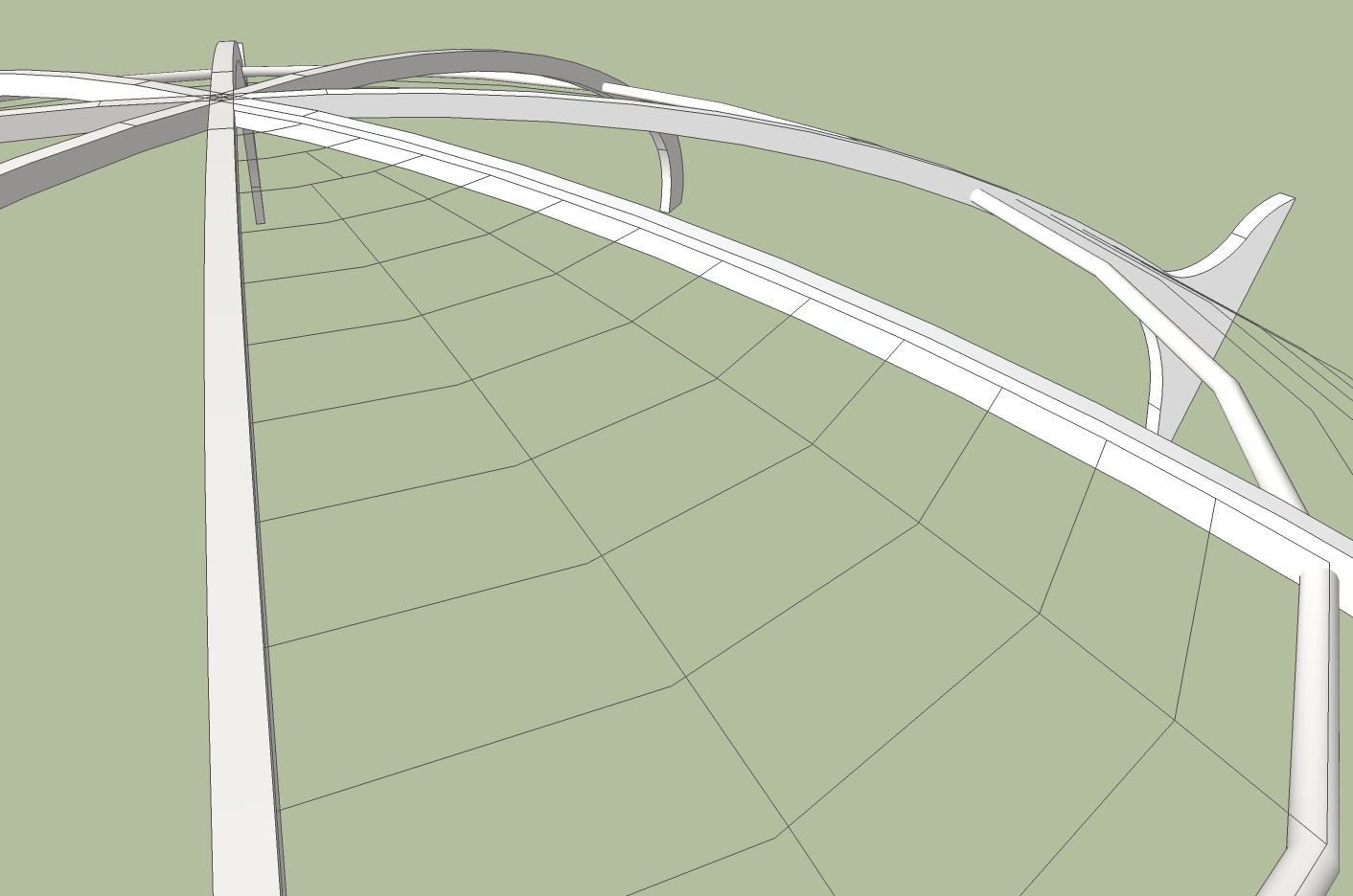
I'm trying to create gridlines representing glass panels in a dome (see attachement). I have 8 curved beams set at 45 degree increments, and I've created the circumferential gridlines using circles with the surface removed, each circle dropped down to follow the curve of the beams. I intend to use one 45 degree "wedge" segment as an object that will be copied into the other 7 inter-beam gaps. Where the circumferential lines intersected with the beams, I drew connecting segments, then deleted the other 315 degrees or each circle. I now needed to create radial divisions to create the actual panels that would be filled with a translucent surface. In order to do this I created a rectangle, grouped it, and stood it on edge. I then moved one corner of the rectangle to the point of the "wedge" and rotated it 15 degrees, then copied and rotated it another 15 degrees. I then drew radial connecting lines between consecutive circumferential arcs, where they intersected the planes. I then deleted the planes. Unfortunately the circumferential arcs still select as a single arc, not three individual arcs. The new lines are for some reason not intersecting with the arcs, or if they are, they are not splitting them. Unfortunately an exported 2D image doesn't retain selection info, so my image doesn't show this. Can someone tell me why this didn't work, or suggest a way to accomplish the task? Thanks!
John

-
Maybe you must initialize your "Polygons circle" with more segments than 24?
For have a more circular form
-
Hi John,
I don't exactly follow why you did what you did. If it' actually a glass dome with some supporting structure, why don't you just run an extrusion along every third radial edge of the dome and forget about replacing the glass part with something you are creating afterwards?
Can you upload your model file?
-
-
Hi Gaieus, hi Jean. Interesting approaches and shows that there are many ways to create the basic dome. If I understand you correctly Gaieus, unlike Jean who creates the support beams, then builds the glass done from a follow-me mid-profile of one of the beams, you are suggesting creating the dome shape first, then extruding, or do you mean using a "follow-me" cross-section of a beam along the length of every third or fourth arc? I'm not sure if "extrude" implies push-pull, and if it does, I'm not quite sure how this would be applied to the segment radial line.
Either way, my problem is that once the basic dome exists, however it was created, I wanted to further subdivide some of the lower panes so that the surface area for any given pane doesn't get too large. I was surprised that when I used vertical rectangles to intersect the circles, then connected the intersection points, the circles still selected as one continuous ring... the radial segments didn't chop the circles into separate segments. Strangely enough, I just did a separate test and it worked fine this time. Anyway, I created a 1/8 segment in my model this way, and got the surface just fine using the sandbox from contours tool. As it was a component used 8 times, I saved a bit of size in a huge model.
It was very worthwhile to hear your different approaches to making the dome, however, a good learning experience. Thanks!
John
-
Well, my approach would not have been too different from Jean's - what I meant was to draw the whole dome first and then use the Follow me tool to extrude a rib along one of the radial lines of the dome. THEN make the radial array. He just made it in a different order (and the "rib" was created differently).
Advertisement


