How to create curved stair
-
Hi,
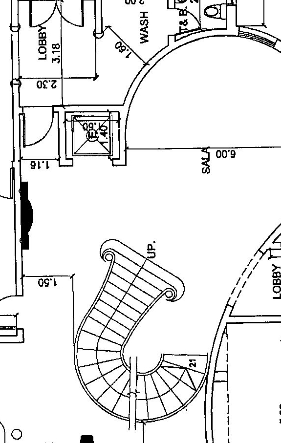
I would like to know the steps in creating curved stair like the attached one.
-
Hi moghamdi,
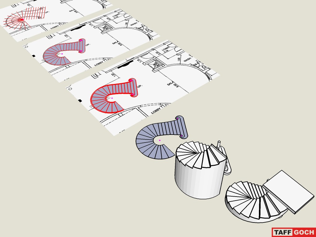
Here's my way (Sketchup file attached).
Sure not the best way, but....
Regards,
Luis
-
Look here http://1oo1bit.com/default.html and in the ruby subforum http://www.sketchucation.com/forums/scf/viewtopic.php?f=180&t=15927
Hope this help you.
Regards
-
thank you all for your support.
-
moghamdi,
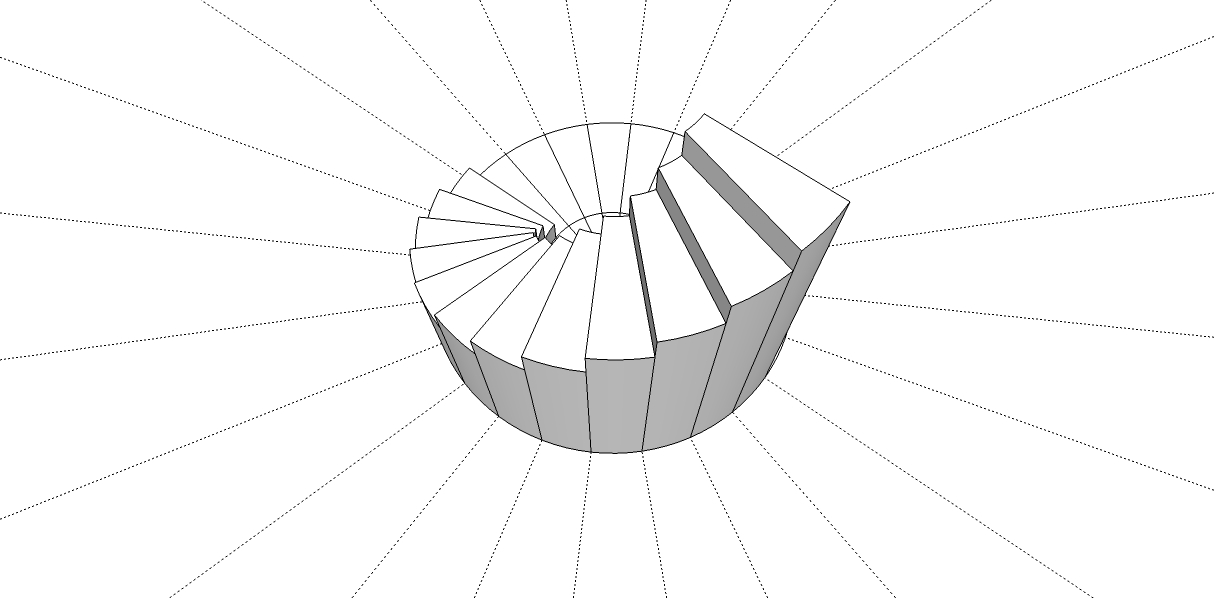
Using the 'push/pull' tool, as described by Luis and his model, can produce nice results, if you have accurately 'traced' the stairs on the original image. Once you have constructed accurate SketchUp edges and faces, flat on the original image, the next task (push/pull) is the easy part.
Note that, with the push/pull tool, after you have pulled up one face, you can double-click on the next step to raise it by an equivalent amount. Double-click again, and it will be raised a second time, by the same increment. Using this tool feature, you can raise subsequent steps by multiple double-clicks.TracingStairs.skp
Taff -
Taff,
Thank you very much for this tutorial, it helped me a lot.
please can you explain how you made the last step??Mohammed.
-
great tut thanks, one question though, how did you place the single verts for your center points.
-
@xrok1 said:
...how did you place the single verts for your center points.
Uhmm, do you mean, how did I place the centerpoints? (I don't know what 'single verts' you're referring to.)
Taff
-
yes the center points.

-
I drew several step edges by eye, to identify the approximate location. I then drew a 'point at intersection' (using the plugin of that name.) After erasing the original 'by eye' edges, keeping one, I rotate/copied that edge, using the array-copy feature of the rotate tool.
If you draw the first edge, then rotate/copy to the last edge position, you can use the rotational array feature of the rotate tool to fill in all the others in between (using the divide symbol in the VCB.) Since twelve steps appear to be rotated in equal increments, type "/12" in the VCB and hit <enter>. This is described in the SketchUp Users Guide, under "Creating Multiple Copies (Radial Arrays)"
All the centerpoints were developed in the same manner -- by eye, then adjusting position until adequate for drawing the correct circle. If the centerpoint wouldn't provide a circle in the correct location, I shifted the centerpoint and circle by smaller-and-smaller increments, until a circle would develop where I needed it (i.e.; trial-and-error experimentation.)
Taff
-
right on, 'point at intersection' is what i was looking for, thanks again.

-
Thanks Taff.
-
Taff,
I follow your description on creating the sloped line. But it looks in your picture that not only are there vertical (hidden) edges at each riser but also mid-step, making the staircase rounder. Is this so? If so it seems the following wouldn't work as the line wouldn't be on the (two) side faces of each step.
@taffgoch said:
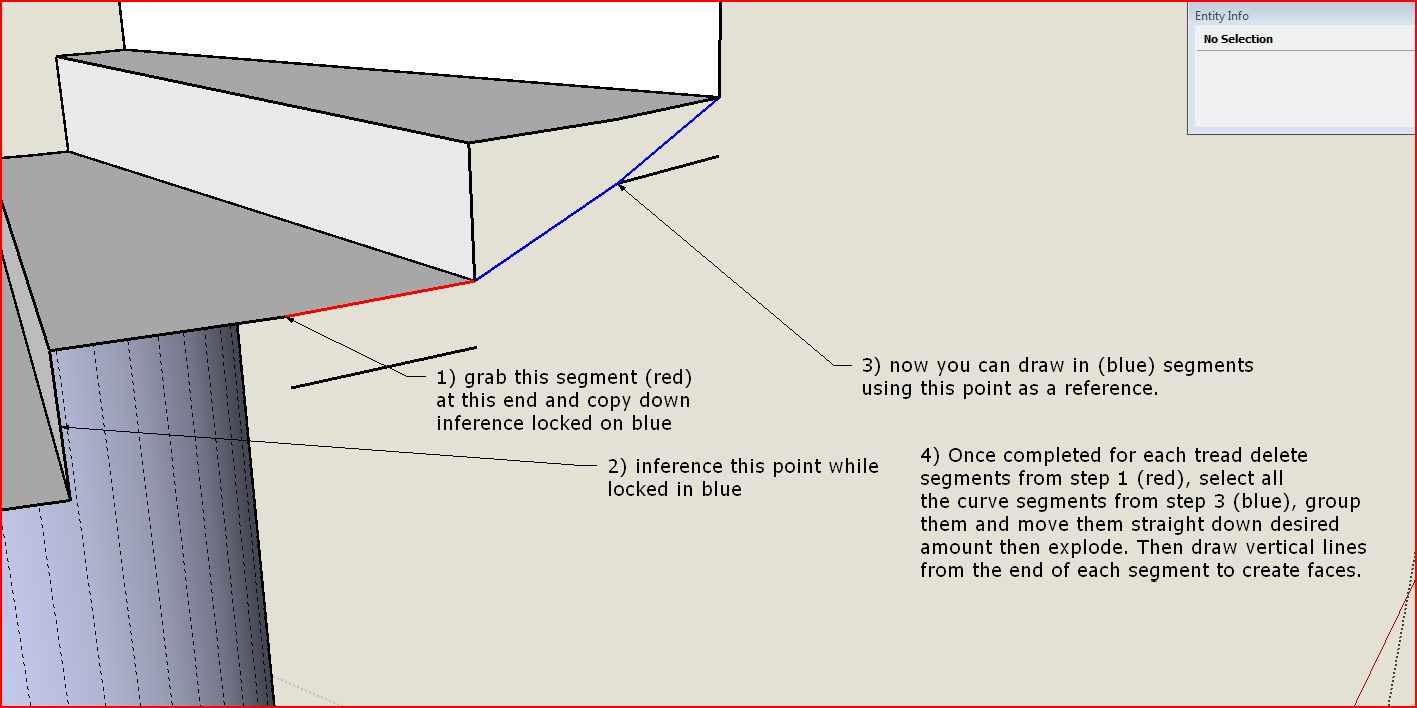
Draw new diagonal line entities from the bottom corner of each step, to the next bottom corner. When done, you can select the new lines, and copy them downward by your desired amount.
Thanks for the tutorial,
Peter
-
pbacot, i had a hard time with this tut for that reason too, i ended up copying half of each tread down that way i got a midpoint for each step when i was tracing the curve.
-
Ooh, sorry about that...
You're right -- I had added an additional endpoint to make the step outer edge 'curved,' instead of straight.
The steps xrok1 describes work well. I actually drew a vertical line from each step 'middle' point, straight down (using the <up> arrow key to limit the line to the 'blue' axis,) and using the midpoint of the vertical edge of the step to set the length of the line. This, essentially, provides the same results as xrok1's method. (You could probably come up with several similar tricks to achieve the same objective.)
Good catch, xrok1. Sorry for the oversight, Peter.
Taff
-
@moghamdi said:
...please can you explain how you made the last step??
Mohammed,
Draw new diagonal line entities from the bottom corner of each step, to the next bottom corner. When done, you can select the new lines, and copy them downward by your desired amount. This will provide the bottom curved line, from the first floor to the second.
Note that I used groups. If you employ the above description while 'inside' the edit of the group, you have to use the copy feature of the move tool, then delete the original curve.
If, however, you keep the group closed, and draw your new diagonals on the 'outside' of the group, the lines won't 'stick' to the group geometry (but inferencing still works.) You can then move the new curved line downwards, without distorting (dragging) the geometry within the group. Once you have the diagonal curve in the new position, select the complete curve and use <ctrl-x> to delete it. This will delete and copy the entities onto the clipboard.
Immediately open the group for editing, and use "Paste-in-place" (Edit menu) to insert the 'deleted' curve into the group's geometry. The rest is cleanup and hand-stitching the underside. (You can use the 'Skin' plugin instead of hand-stitching.)
EDIT: See several posts down, for clarification regarding the rounded steps having two lines defining the outer edge. To draw the diagonals, this middle point has to be included, as well. xrok1 describes one method. [Sun Feb 15, 2009 5:20 pm]
Taff
Hello! It looks like you're interested in this conversation, but you don't have an account yet.
Getting fed up of having to scroll through the same posts each visit? When you register for an account, you'll always come back to exactly where you were before, and choose to be notified of new replies (either via email, or push notification). You'll also be able to save bookmarks and upvote posts to show your appreciation to other community members.
With your input, this post could be even better 💗
Register Login


Advertisement