Help! Camera Issues - After Downscale
-
Hi all,
Thanks very much for your time. I'm hoping to acquire some advise from the experts regarding a camera clipping issue that seems to be the result of a downscaling operation.
I have developed a motorcycle part at x1000 scale. After downscaling to it's finished size my camera is bugging out. I can orbit, but not pan and when I attempt to open the group all geometry disappears. I think the viewport still recognizes the model at it's larger scale which I've gathered from another posted discussion. Unfortunately the steps described in this discussion aren't working for me. More likely, I'm simply not executing them properly.
Here is the model for download; https://www.dropbox.com/s/tto2q2n02p33zdo/Model%20-%20Camera%20Clipping%20Issue.skp?dl=0
Line segments in the model are very small, so I'm not surprised that the viewport lags a bit. The part has been developed for SLA prototyping. I've developed many other parts this way, but I've never experienced this camera issue. I'm hoping someone may have some time to check it out and share their expertise.
Thanks again,
Stefan Mortveit
-
Components have a rightclick option to Scale definition. Groups don't have this so it is easiest to simply explode and regroup it.
-
Thanks Box,
I attempted the ungroup - regroup operation and it does fix the camera issues. However, the model looses some of the smaller line segments and faces, and when I try to redraw funny things happen. The face geometry starts changing and I cannot seem to get anything to stick. Weird. Any other thoughts for me?
Thanks again for your time.
Stefan Mortveit
-
You have too many segments, more that you would even need for SLA printing and you will always get issues working so small.
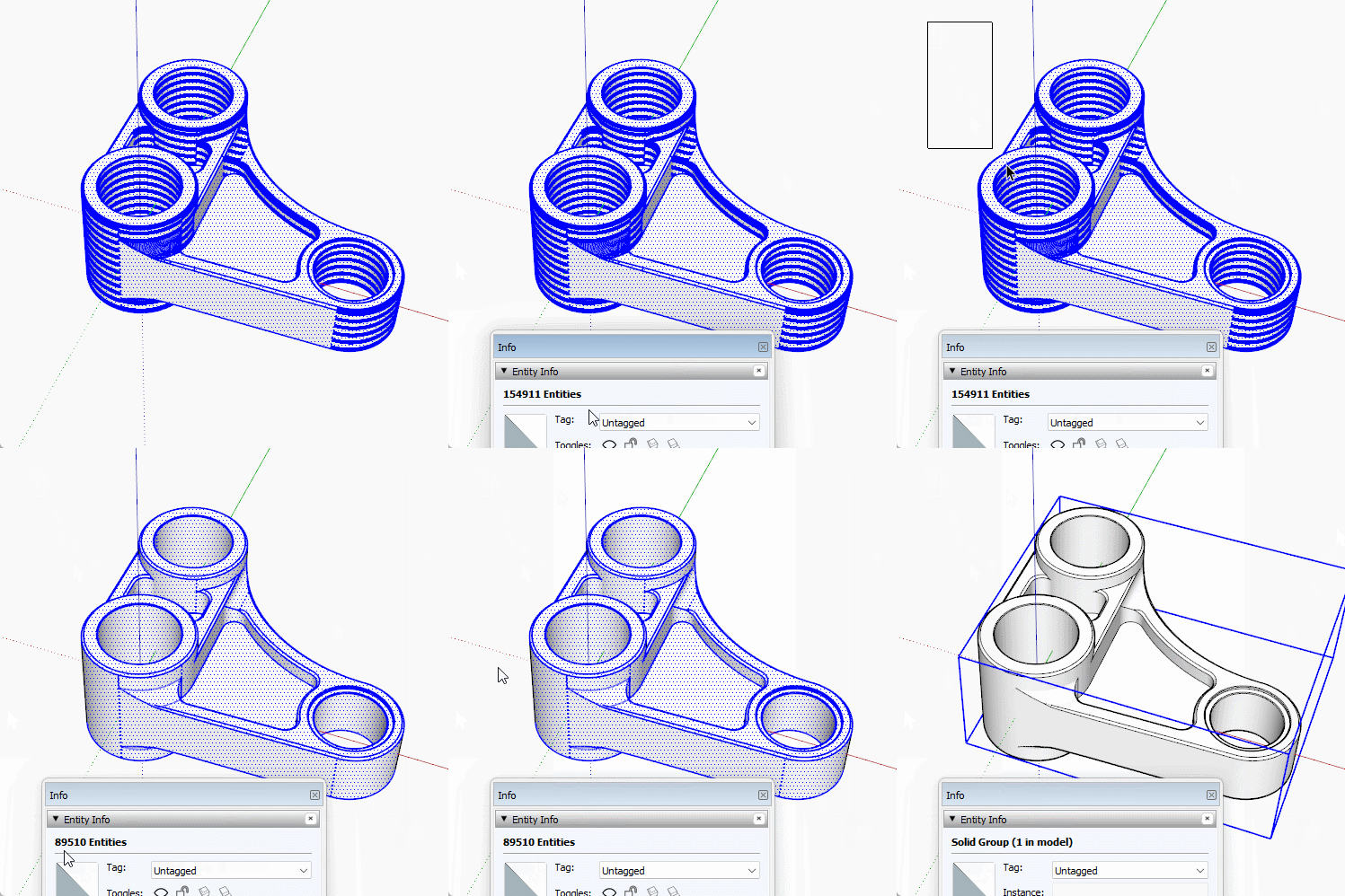
However, if you explode, then fence select the whole thing and Group it you shouldn't miss the edges and faces you are currently missing.It is also worth thinking about working at a larger scale and not scaling down. I'm guessing you are exporting .stl files for printing. They are unitless. So you can have a model in meters but tell the printer it is mm and away you go.
-
Here's a quick gif to show you it works for me, if it's not working for you then there is another issue.

-
Thanks Box!
I've got it sorted. I appreciate your time in walking me through the process. A few more questions for you.
First, do you know if CNC milling machines can reset dimensions in the same way you've described for .stl printing files? I'm not sure what's required at the machine, but fabrication companies ask me for a .step or .iges which I generate from my .stl files with FreeCAD. Perhaps there's a better way to do this?
Second, in order to create the stop chamfer on the edges of the model where there is a radius transitioning into a perpendicular surface (ball-end mill). I have been manipulating a 45 degree face with a radial bending tool to pull off the edge at a point. Then deleting everything except for one welded line as the desired path. Followed by recreating a triangular shape and running the follow me tool. Finally subtracting the solid chamfer shape from the solid body. Is there a better way to do this?
Thanks again for all your help.
Stefan Mortveit
Advertisement


