Marking Internal Volume
-
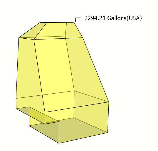
OK, I have this container, and I wish to have black paint markings on the inside walls of the container that indicates the amount of spill oil the container has captured. This container is to be installed underwater and will capture the small leakage while some items are being repaired. There will be internal cameras installed, such that the topside crew can observe the amount of captured oil and the time frame from one mark to another. This will give the topside crew and idea if the leakage is increasing and other actions need to be taken.
I have looked at all the plugin for volume, none seem to fill the bill. I have decided to take the total volume, divide by ten and have ten marks on the inside walls of equal volume. That is number #1 marking one will have the same volume as markings between #9 and #10. The markings can be in cu/ins, cu/ft or gals.
So, if you know of a plugin that I haven't seen, any help would be appreciated.
Thank you in advance for your help.
Ken

-
Hi Ken
I came up with this method which may suit your proposed application - not 100% accurate but could be okay for underwater!
Use ordinary volume calcs for the rectangular parts of the unit. Isolate the tapered mid section (yellow in the screenshot) and group so its volume appears in the Entity info tab. (The top tapered section will be a similar exercise.)
Slice the yellow shape into, say, 10 equal thickness horizontal slices and make each slice a separate group so that each can have its volume noted.Construct a graph (see screenshot) with Volume on the X axis and Height on the Y axis. That should be the other way round logically now that I think about it but the result will be the same. In my graph Volume is in units of 'one m3' but for the Height I increased the unit distance by a factor of four just to make it easier to read. Plot the equal slices on the Height axis starting with the top most slice at the '0' x/y point. Click on each slice and read off its volume. Plot each volume on the Volume axis, I used a dot with cross made into a component. I then used a Cubic Bezier curve (BezierSpline by Fredo6) to join up the plotted volumes. Hide or erase the dots and retain the curve.
Just for convenience, I scaled the oil tank drawing so that it was approximatley 40m3 and this would allow for 10 levels of 4m3 to be marked. So now, by using the measuring tool to intersect the plotted curve at each required volume (4m3 in this case), the corresponding thickness of each 4m3 slice can be read off along the Height axis. (A division by 4 is needed to get the correct measurement having made the height units wider.)
I used 1001Bit Pro tools to alter the thicknesses of the slices - 'Extrude selected profile - maintain taper'. Saves a bit of work but can still be done with native SU tools of course. Check each new slice for volume. I think some levels will contain both rectangular and irregular geometry so some adding/subtraction needed.
The tank can be marked from the new slices - I haven't shown this. No doubt there will be a maths guru out there who could come up with a formula but this is as good as it gets!
Hope this is useful and reasonably intelligible, if not it kept me happy for an afternoon/evening!
Kind regards
-
Thank you for the info. I tried dived and conquer. However, the changes in the sides angles prevented me using graphing or ratios.
However, one of the plugin writers solved the problem. I will let the plugin writer make himself known.
Again thanks for the info.
Ken
Advertisement


