Newbie question: extrude following a straight line in space
-
Hello,
sorry, I've got a probably quite stupid newbie question:I am trying to extrude an aluminium profile along a line
in space.
So e.g. my "line in space" goes from 0,0,0 to 5,5,5.
The "profile" shall be a rectangle of 0.1, 0.1, 0.2
The "profile" shall hang on the underside of my line
(exactly in the middle).How can I tell Ruby to draw this rectangle perpendicular
to the "line in space", so I can extrude it afterwards?
The upper edge of the "profile" would be level with
the plane of the x and z axis and perpendicular to the
"line in space"It's probably be done with the cross product of my
"line in space" and a second vector. But how to to
calculated the projection of the "line in space" on
the plane (so that I can find out the angle relativ
to the world axis).Or is there an easier way by creating a new coordination
system with the "line in space" as one of the axises?Sorry for my English (which is excellent compared to my Ruby
 .
.
By the way, thanks to everybody who invested in the various tutorials
and postings here - it did help me a lot to get that far!Best regards
Klaus -
I do not know your purpose of the plugin, but it seems like you would want to create a ComponentDefinition from the extruded profile so the Component could be re-used without re-drawing it each time.
Typically, you would draw the extrusion in the definition along an axis, then place the component and rotate it to the desired position.
-
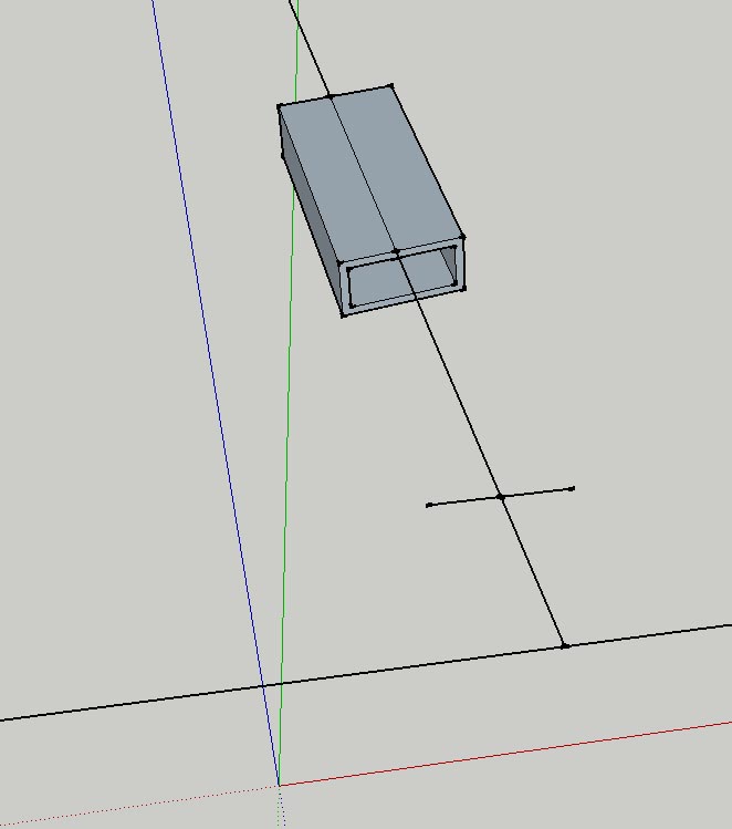
Hello Jim,
I got a problem to code it. The principle is understood, but I am not able to get to the code.See the picture below:
First I draw the long line going up (angle and length are different every time, depending on some input parameters, but it's not parallel to any axis).
Next I would like to draw the two lines left and right, parallel to the red axis.
Then I would liek to draw more line to make it two rectangles and
that rectangle I would like to extrude for some mm.But I am already stuck at finding out, how to make these first two lines,
at 90° and parallel to the red axis.
-
If the long line "is not parallel to any axis" then the 2 lines left and right can not be both perpendicular to the long line and parallel to the red axis. The 2 lines left and right must be either perpendicular to the long line OR parallel to the red axis, but not both.
Do you mean you want the 2 lines left and right to be perpendicular to the long line and parallel to the ground plane?
-
Hopfully this is helpful:
model = Sketchup.active_model line = model.selection[0] w = 2.0 l = 1.0 pts = [ [-w/2 , -l/2 ] , [w/2 , -l/2 ] , [w/2 , 0 ] , [-w/2 , 0 ] ] z_axis = line.end.position - line.start.position l_len = z_axis.length z_axis.normalize! if z_axis == Z_AXIS or z_axis == Z_AXIS.reverse x_axis = z_axis.cross(Y_AXIS).normalize else x_axis = z_axis.cross(Z_AXIS).normalize end y_axis = x_axis.cross(z_axis).normalize tr = Geom;;Transformation.axes(line.start.position, x_axis, y_axis, z_axis) pts.map!{|pt| pt.transform!(tr)} face = model.entities.add_face(pts) face.reverse! face.pushpull(l_len) -
Hello Jim,
this is great, thank you very, very much! I see a long way of
learning ahead of me
I can continue with my program now!However, just out of curiosity:
Why do I need to use a different axis for the cross product
if the selected line is very steep, or rather why
exactly 1/64th is the true/false - point? Testing it,
the extruded from flips by 90°, but I can't get my
head around it - why?Best regards and thanks again!
Klaus -
The 1/64 I may have made up, or borrowed from the AutoCAD arbitray axes formula. It is probably not needed. It should work to simply compare the line to the Z_AXIS. If the line is the Z_AXIS, we need to use another axis in the cross product calculation.
-
Ah! ok, then I understand it.
Thanks again!
Hello! It looks like you're interested in this conversation, but you don't have an account yet.
Getting fed up of having to scroll through the same posts each visit? When you register for an account, you'll always come back to exactly where you were before, and choose to be notified of new replies (either via email, or push notification). You'll also be able to save bookmarks and upvote posts to show your appreciation to other community members.
With your input, this post could be even better 💗
Register Login


Advertisement